Regional Settings Guide These instructions are used for both the Open xL and Monitor xL versions of xL Security Equipment. A red dot on xL equipment and its packing material will identify it as the Open xL version. rev1.
Contents WARNING: Access Control, Suite Security and Elevator selections are only available with the addition of the “Feature Expansion Board” to the system. Document Revision History .........................................................................................................................ii Powering on the System for the First Time................................................................................................1 Understanding How to Program the System Using the LCD Keypad....
General Message Format ...............................................................................................................106 SIA Level II Format.....................................................................................................................106 Contact ID Format ......................................................................................................................106 Door Activity.................................................................................
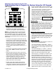
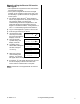
Powering on the System for the First Time Understanding How to Program the System Using the LCD Keypad service technician: “000”. “Service, Enter PIN:” will appear. Enter the default service user’s pin: “2482” LCD Keypad: • The next screen will say: “Configure?” and give a selection for the mode in which you want to configure the system. The first selection is “Locally” meaning the system can be configured using the keypad only.
(remain on the premises with only the perimeter protection on) or On (all protection turned on) pressing the keypad button below them. Press the right arrow key to browse through the Menu Options. Selections such as Status (condition of system), Bypass (disable a protection point), History (alarm etc.
Manually calling the Director PC from the LCD Keypad: • • This operation is for systems that can communicate with the Director software. If the system configurations have been changed example: by the customer to add a new user, it will be necessary to update the Director configurations for the system. 1) The system Unique ID and 3rd Party Password have to be programmed in the system if they were not previously.
Special Regional Settings Keypad Operations For all xL Security System keypad operations, refer to the “xL LCD Keypad User’s Guide” North America • Split Logs When the History menu is accessed on the keypad, the selections “All”, “Intrusion” and “Category\Area\Area condition: On, Off, Stay\Area History” are available. European • • • • • If the system is not ready to arm when logging on to the keypad, the message: “check system” will appear on the keypad screen.
• Entry/Exit Delay The system timer delay tables for a China/HK regional setting replaces 45 seconds with 40 seconds and 90 seconds with 100 seconds for “CCC” requirements. Netherlands • • • • Dual Custody A service user entering their user codes must also have an end user enter their user codes for the service user to be able to service the system or access system programming through the keypad.
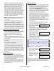
Entering and Understanding Simplified Configurations • Logon to the system as a service user. Default ID: “00 or 000”, service user PIN: “2482”. • When the control box tamper is activated, a service user has LCD Screen Service Enter PIN: _ _ _ _ the authority to access system programming. • • • • • • • 6 Using the left and right Menu Options arrow screen scrolling ◄ Config ► ↓Ok keys on the keypad scroll the menus until Config is displayed. Press Ok. “Config method” will display.
Simplified Configurations Simplified Programming System Global Timer Delay Table 0 seconds 1 seconds 2 seconds 3 seconds 5 seconds 10 seconds 15 seconds 20 seconds 30 seconds (45 seconds China/HK = 40 seconds) 60 seconds (90 seconds China/HK = 100 seconds) 2 minutes 3 minutes 5 minutes 10 minutes 15 minutes 20 minutes 30 minutes 45 minutes 60 minutes 90 minutes 2 hour System Siren Time Selections: Delay Table Main Screen Greeting Selections: Type entry PIN Duress Selections: Yes/No 5 Digit PIN Sel
Communications Telco Modem Type Selections: Bell 103, 8OPSTU (REDCARE), WW Modem, WW 8OPSTU, None. Enable Line Fail Selections: Regional Setting Default: N America Bell 103 European WW Modem U.K. ACPO WW 8OPSTU Aus/NZ WW 8OPSTU China/H.K. WW Modem Netherlands WW Modem Switzerland WW Modem France WW Modem Regional Setting Default: N America No European Not Used U.K. ACPO Not Used Aus/NZ Not Used China/H.K.
Number of Rings to Answer Selections: Defeat Answering Machine Selections: Yes/No Selections: Yes/No Regional Setting Default: N America 08 European 04 U.K. ACPO 02 Aus/NZ 14 China/H.K. 04 Netherlands 04 Switzerland 04 France 04 Regional Setting Default: N America Yes European Yes U.K. ACPO Yes Aus/NZ Yes China/H.K. Yes Netherlands Yes Switzerland Yes France Yes Regional Setting Default: N America No European No U.K. ACPO No Aus/NZ No China/H.K.
Area Report Mode Selections: Full, Emergency Bell Squawk Selections: None, On Regional Setting Default: N America Emergency European Emergency U.K. ACPO Emergency Aus/NZ Full China/H.K. Emergency Netherlands Emergency Switzerland Emergency France Emergency Arming, Fail to Arm, Both. Regional Setting Default: N America None European Fail to Arm U.K. ACPO Fail to Arm Aus/NZ None China/H.K.
Exit Delay Level Selections: Stay+On, On Tone Warnings Selections: Yes/No Only, None. Regional Setting Default: N America Stay+On European Stay+On U.K. ACPO Stay+On Aus/NZ Stay+On China/H.K. Stay+On Netherlands Stay+On Switzerland Stay+On France Stay+On Regional Setting Default: N America Yes European Yes U.K. ACPO Yes Aus/NZ Yes China/H.K. Yes Netherlands Yes Switzerland Yes France Yes Annunciate Area Map (Keypad tones) Press the button below “ÈEdit “ to make changes.
Input Points Point Types: EE(entry/exit)Door, EE Route, Perimeter, Motion, Fap Motion, Day Warning, Burglary, Fire Class A, Fire 15s (second), Fire 0s (immediate), Hold-up, Aux Alert (auxiliary alert/emergency), Supervisory, Local 24h (hour), Lcl StayOn (Local Stay-On), Lcl Stay20n, Local On Only, undefined. FAP: (False Alarm Preventer) If a FAP input is not OK longer than 10 seconds, an alarm condition occurs. If a FAP input is triggered and immediately resets, a 20 minute timer begins.
main control board. European U.K. ACPO Aus/NZ China/H.K. Netherlands Switzerland France Point 006, N America main control board. European U.K. ACPO Aus/NZ China/H.K. Netherlands Switzerland France Point 007, N America main control board. European U.K. ACPO Aus/NZ China/H.K. Netherlands Switzerland France Point 008, main control board. N America European U.K. ACPO Aus/NZ China/H.K. Netherlands Switzerland France 21-3609E rev1.
Point 009, N America main control board. European U.K. ACPO Aus/NZ China/H.K. Netherlands Switzerland France Point 010, N America main control board. European U.K. ACPO Aus/NZ China/H.K. Netherlands Switzerland France Point 011, N America main control board. European U.K. ACPO Aus/NZ China/H.K. Netherlands Switzerland France Point 012, main control board. N America European U.K. ACPO Aus/NZ China/H.K.
Point 013 First keypad alert button. Point 014 Second keypad alert button. Point 015 Third keypad alert button. Points 016 – 256 undefined. N America China/H.K. Netherlands Switzerland France N America European U.K. ACPO Aus/NZ China/H.K. Netherlands Switzerland France N America Fire 0 second, no delay Undefined Undefined Fire 0 second, no delay Undefined Undefined Undefined Undefined Hold-Up Undefined Undefined Hold-Up Undefined Undefined Undefined Undefined Auxiliary Alert European U.K.
Switzerland 1 second OFF9STAY9ON9 OFF9STAY9ON9 OFFSTAYON France 1 second OFF9STAY9ON9 OFF9STAY9ON9 OFFSTAYON Transmit Sonalert Siren E03 AC Mains Failure Regional Setting Defaults Time Delay N America 4 hours OFF9STAY9ON9 OFF9STAY9ON9 OFFSTAYON European 60 minutes OFF9STAY9ON9 OFF9STAY9ON9 OFFSTAYON U.K. ACPO 4 hours OFF9STAY9ON9 OFF9STAY9ON9 OFFSTAYON Aus/NZ 30 minutes OFF9STAY9ON9 OFF9STAY9ON9 OFFSTAYON China/H.K.
European Undefined OFF9STAY9ON9 OFF9STAY9ON9 OFFSTAYON U.K. ACPO Undefined OFF9STAY9ON9 OFF9STAY9ON9 OFFSTAYON Aus/NZ Undefined OFF9STAY9ON9 OFF9STAY9ON9 OFFSTAYON China/H.K.
Switzerland 1 second OFF9STAY9ON9 OFF9STAY9ON9 OFFSTAYON9 France 1 second OFF9STAY9ON9 OFF9STAY9ON9 OFFSTAYON9 Transmit Sonalert Siren E12 Module (Pod) Battery Low Regional Setting Defaults Time Delay N America 1 second OFF9STAY9ON9 OFF9STAY9ON9 OFFSTAYON European 1 second OFF9STAY9ON9 OFF9STAY9ON9 OFFSTAYON U.K. ACPO 1 second OFF9STAY9ON9 OFF9STAY9ON9 OFFSTAYON Aus/NZ 1 second OFF9STAY9ON9 OFF9STAY9ON9 OFFSTAYON China/H.K.
European Undefined OFF9STAY9ON9 OFF9STAY9ON9 OFFSTAYON U.K. ACPO Undefined OFF9STAY9ON9 OFF9STAY9ON9 OFFSTAYON Aus/NZ Undefined OFF9STAY9ON9 OFF9STAY9ON9 OFFSTAYON China/H.K. Undefined OFF9STAY9ON9 OFF9STAY9ON9 OFFSTAYON Netherlands Undefined OFF9STAY9ON9 OFF9STAY9ON9 OFFSTAYON Switzerland Undefined OFF9STAY9ON9 OFF9STAY9ON9 OFFSTAYON France Undefined OFF9STAY9ON9 OFF9STAY9ON9 OFFSTAYON 21-3609E rev1.
Outputs Pre-programmed Output Select Output? numbers like B001 will ◄ B001 ►S000.07 ↓Ok display with their preprogrammed code: e.g. S000.07. This is an output code that is programmed in Advanced Programming. Press ↓Ok to edit the pre-programmed output using the following simplified output selections.
B002 (Relay 2 on motherboard) B002 (Relay 2 on motherboard) B002 (Relay 2 on motherboard) B003 (keypad) Netherlands (S000.57) Switzerland (S000.05) France (S000.05) N America (Advanced programming code: A001.01) System Fully On (Strobe) Normal System In Alarm Normal System In Alarm Normal Areas A01: OFFICE Function Key 1 on Area 1 st 1 keypad. Positive Trigger, 10 sec delay. NOTE: A complex output like this must be programmed in Advanced Programming. Normal B003 (keypad) European (A001.
Outputs (UK version) Select Output B001 – B128 Select Group (Program Section) System B001 – B128 Areas Select Area # B001 – B128 Protection Points Select Point # B001 – B128 Outputs Select Output # Modules Select Module # Equipment Points Select Point # B001 – B128 B001 – B128 Select Condition Select Operation Fully On, In Alarm, Siren, Fire Cadence, Was In Alarm, ACPO Fire, ACPO Attack, ACPO Unconfirmed, ACPO Set, ACPO F/Faul (Fire Fault), ACPO Bypass, ACPO Confirmed, ACPO Siren, ACPO Strobe.
Circuits Input Circuit Types and Defaults (Also programmable in Advanced Programming, Section S007:00) Regional Setting Select Circuit Circuit Name Pre-Programmed Resistor Configurations Type Enter Custom Resistor Values (TYPE1 NC, TYPE2 NO, TYPE3 NC Single Series ,TYPE4 NC Single Parallel , TYPE5 NO Single Series , TYPE6 NO Single Parallel ,TYPE7 NC Dual Type 1 , TYPE8 NC Dual Type 2 , TYPE9 NO Dual Type 1 , TYPE10 NO Dual Type 2) N America European U.K. ACPO Aus/NZ China/H.K.
Circuits France 24 C01 C02 Normally Open Normally closed dual type 2 2 8 C03 N0 2 K = ALM 1 K = OK TYPE2 2K2EOL NC Dual Type2 8 C04 TYPE2 8K2EOL NC Dual Type 2 8 xL Regional Settings Guide No resistor R1 (ohms) 00000 R1 (ohms) 00000 R1 (ohms) 00000 R2 (ohms) 00000 R2 (ohms) 00000 R2 (ohms) 00000 21-3609E rev1.
Entering and Understanding Advanced Configurations • Logon to the system as a service user. E.g. Default ID: “000”, service user PIN: “2482” or “7378” if the panel has communicated with the Director Software. NOTE: If the system Feature Set (S002È00) is 5 or greater, keypad programming can not be done. Programming can only be done with the Director Software. NOTE: Default MASTER (end) USER code is ID 01 or 001, PIN 7793.
Advanced Program Sections, Sub Program Sections and Selections NOTE: For quick reference to locate Advanced Programming Section Selections, consult the Index at the back of this manual. WARNING: Access, Elevator and Suite Security selections are only available with the addition of the “Feature Expansion Board” to the System. Programming selections whose boxes are grey are not available for this version.
Module Bus (SNAPP) Baud Rate 0 = Auto Minimum (19K2), 1 = Auto Maximum 38K4 The communications speed between the main panel and the expansion modules. Suite Security (Condo) Baud Rate 0 = Auto Minimum (19K2), 1 = Auto Maximum (38K4) 2 = 9600 (Auto Minimum), 3 = future. The communications speed between the main panel and the Suite Security modules. NOTE: This feature is only available with the addition of the Director Software and Feature Expansion Board.
S001È02 Keypad Selections Auto Update Card 9Allow automatic version Version update. NOTE: This feature is only available with the addition of the Feature Expansion Board. □ Delay Screen 9(yes) □ (no) Fast Restore 9(yes) □ (no) Disable update Whether or not replacement cards are to be granted entry, and the system is to be updated with the higher version number automatically. (This setting refers to fixed-ID cards with a version number). If a point restore is to be sent within 1 min.
S001È03 Keypad Selections (left to right on keypad screen) Name Selections Description This is a security ‘key’ that 3rd Party Password blocks an unauthorized connection to this panel i.e., by a PC running another copy of the Director software. S001È04 Keypad Selections (left to right on keypad screen) N America Example: N America European U.K. ACPO Aus/NZ China/H.K.
S001È04 Keypad Selections Confirm Reset 9(yes) Service □ (no) Confirm Reset Master 9(yes) □ (no) Confirm Reset Challenged PIN. 9(yes) □ (no) Confirm Reset using Remote 9(yes) □ (no) N America European U.K. ACPO Aus/NZ China/H.K. Netherlands Switzerland France N America European U.K. ACPO Aus/NZ China/H.K. Netherlands Switzerland France N America European U.K. ACPO Aus/NZ China/H.K. Netherlands Switzerland France N America European U.K. ACPO Aus/NZ China/H.K.
AC Sync 0=60 Hz, 1=50 Hz, 2=No sync required, 3=DC supply AC Brownout Mode 0=None, 1=Local alarm, 2=Alarm+report, 3=Report only Synchronization with AC line to maximize internal clock accuracy. With an unstable AC source, select "2: AC-No Sync" ('AC failure' will be reported if the frequency drops below 12.5 Hz). With a DC source, be sure to disable E003 (AC Trouble) under "Equipment Settings".
S001È07 Keypad Selections (left to right on keypad screen) N America Example: 00·00·0·0·0· ······ ÈSave S001È07 Name VBUS Panel # Outputs Selections Paging # Outputs 0=0, 1=2, 2=4, 3=6, 4=8, 5=10, 6=12, 7=14, 8=16 Also see S005:08, 09 Main Panel Plug In Board Outputs 0=0, 1=2, 2=4, 3=6, 4=8 Also see S005:08, 09 VBUS Mode 0 – 3 future NOTE: Programming selections whose boxes are grey are not available for this version.
S001È08 Keypad Selections (left to right on keypad screen) Name Selections Description 0 – 127 days Delinquent Arming Delinquent Account Threshold Protection. Tracks panels that have not been operated for the number of days selected. Area Group Mode 0=By area arming only 1=User Groups Only: users can turn on protection to all groups of areas they are authorized for. 2=Manual + User Groups: users can turn on protection to all groups of areas they are authorized for, individual area groups or areas.
S002È00 Keypad Selections (left to right on keypad screen) Name Selections Description Operation Mode 0- Standard version 1- European with modem support 2- UK (DD243) (ACPO) 3- Australia 4- China/Hong Kong 5- Netherlands 6- Switzerland 7- France Feature Set 1-14 from the following table. This setting determines the system capacity.
S002È01 Keypad Selections (left to right on keypad screen) N America Example: 0·0·0· 9 999 · ÈSave S002È01 Name User Logon Mode Selections Description Regional Settings Default 0 = Standard user ID logon or Card Number logon: 1 = 4 digit, 2 = 5 digit, 3 = 6 digit, 4 = 7 digit, 5 = 8 digit 6 = 9 digit, 7 = 10 digit Users can enter their card # at LCD keypad & keypad readers.
S002È01 Keypad Selections Blind Card 9(yes) Re-enrollment □ (no) Meaningful only if using card enabling feature Supports Intrusion 9(yes) □ (no) System Type. Viewing only. Dependent on setting in Director Software. System capacity. Supports Access 9(yes) □ (no) System Type. Viewing only. Dependent on setting in Director Software. Supports Central Station 9(yes) □ (no) System Type. Viewing only. Dependent on setting in Director Software.
S002È02 Invalid Cards and PINs Detection Selections Keypad Selections (left to right on keypad screen) N America Example: 12·12·09·5·0·3· ÈSave Name Reset Timeout S002È02 Selections Delay Table Description Regional Settings Default The period of time required before there are no further invalid PIN/cards and an “Invalid PIN/Card Condition” resets. Delay Table The length of time a user is locked out of the system after X number of invalid PIN/Card tries are made, even if a valid try is made.
S002È03 Keypad Selections (left to right on keypad screen) Name Selections Description Delay time. Delay table. Point Reset Time Language Set 0=Eng,Fre,Dut,Spa, 1=Eng,Slk,Slk,Slk, 2=Future, 3=Future Remote FW Down/Up Load 0 = Allowed, 1= Must be authorized Arming Rules 0 = Normal operation. Entry/Exit keypad standard tone. 1 = Disarm to off by token. Entry/Exit keypad standard tone. 2 = Constant keypad Entry/Exit tone 3 = Disarm to off by token. Constant keypad Entry/Exit tone.
S003È00 Primary Card Format—Site Code Checking WARNING: S003È00 – S003È05 Access Control related selections are only available with the addition of the “Feature Expansion Board”.
S003È03 Keypad Selections ID Number Length 01 – 32 No. of Bits / Chars 01 – 40 Bits per Character 01 – 08 Card/Token Format 0=none, 1=future (dallas), 2=Weigand, 3=Magstripe The length of the card ID-number for primary-format tokens. The total number of bits (Wiegand) or characters (Magstripe) in the card data. The number of bits used to represent each character (for magnetic stripe cards). The basic type of card or token associated with the primary card format settings.
S004È01 Secondary Card Format—Site Codes Keypad Selections (left to right on keypad screen) Name Selections Description 1st Site Code Value 0000 – 9999 2nd Site Code Value 0000 – 9999 3rd Site Code Value 0000 – 9999 Regional Settings Default The 1st of up to three site/system codes that can be encoded within access tokens to be used at the site. The 2nd of up to three site/system codes that can be encoded within access tokens to be used at the site.
S004È04 Secondary Card Format—Odd-Parity Checking Keypad Selections (left to right on keypad screen) Name Selections Description Odd Parity Position Odd Parity Start 1 – 40 Odd Parity Length 0 – 40 1 – 40 Regional Settings Default The position of the odd-parity 'checksum'. This is the position of the first data-bit to be included for odd-parity checking. 26 (U.K. ACPO = 00) If either the odd parity length = 0 or even parity length = 0, then parity will not be checked. 12 (U.K. ACPO = 00) 14 (U.K.
S005È00 Keypad Selections 0: ULC Telco Sequence 1: UL compatible 2: Long 3: MONITOR Standard (in Canada use 0 or 3) Call Sequence Details: (P = Primary phone # attempt; B = Backup phone # attempt) 0 (ULC): PPBBPPBB / delay 60 min / PPBBPPBB / delay 60 min / PPBBPPBB / delay 60 min / PPBBPPBB. 1 (UL): PPBBPPBBPB / delay 10 min. 2 (Long): PPPPBBBB / delay 10 min / PPPPBBBB / delay 30 min / PPPPBBBB / delay 60 min / PPPPBBBB / delay 2 hours / PPPPBBBB.
S005È03 Keypad Selections (left to right on keypad screen) N America Example: Name Telco Country Code Selections 010········ ÈSave S005È03 Description Regional Settings Default N America European U.K. ACPO Aus/NZ China/H.K. Netherlands Switzerland France 001 = Argentina … 088 = Yemen.
S005È06 Keypad Selections Telco Modem Init String (left to right on keypad screen) Name Selections Description NOTE: Programming selections whose boxes are grey Telco Modem Init (16 characters) are not available for this version.
S005È08 Keypad Selections (left to right on keypad screen) Name Paging Mode Selections 0 = None 1 = Numeric SemaDigit w/ HS 2 = Blind SemaDigit 3 = SemaPhone (future) Description Regional Settings Default Also see S001:06, 07 Paging Output Data 9(yes) □ Also see S001:06, 07 N America European U.K. ACPO Aus/NZ China/H.K. Netherlands Switzerland France N America European U.K. ACPO Aus/NZ China/H.K.
mode Main Control Board BaudRate 0=AutoMin(38K), 1= AutoMax (115K), 2=AutoMin (56K), 3=future Main Control Board Config Dial Out 0 = No config dial out, Configurations dial out from main control board to Director software PC. Internal: main control board plug in modem.
Feature Expansion Board. Suite Security Telco Reporting 0=None, 1=Condos report alarms etc. over telco dialer NOTE: This feature is only available with the addition of the Director Software and Feature Expansion Board. Main Control Board Answering Machine Defeat 9(yes) □ (no) Main Control Board Config Callback Only 9(yes) □ (no) Used with North American or World Wide Modems. Netherlands Switzerland France N America European U.K. ACPO Aus/NZ China/H.K.
S005È15 Keypad Selections 00 = midnight Telco Comms Test Hour The time (hour) for communications tests to occur. Telco Comms Test Minute 0-59 The time (min.) for comms tests to occur. Telco Comms Test Day 0=Sun … The day for weekly comms tests to occur. N America European U.K. ACPO Aus/NZ China/H.K. Netherlands Switzerland France N America European U.K. ACPO Aus/NZ China/H.K. Netherlands Switzerland France N America European U.K. ACPO Aus/NZ China/H.K.
S007È01, 05, 09, 13 Circuit Band Definitions (Custom Resistor Values) Keypad Selections (left to right on keypad screen) N America Example: 0·1·1·1·1········ ÈSave Name Selections Band 1 Band 2 Band 3 Band 4 Band 5 0=Normal, 1=Alarm, 2=Tamper, 3=unused 0=Normal, 1=Alarm, 2=Tamper, 3=unused 0=Normal, 1=Alarm, 2=Tamper, 3=unused 0=Normal, 1=Alarm, 2=Tamper, 3=unused 0=Normal, 1=Alarm, 2=Tamper, 3=unused Description S007È02, 06, 10, 14 Circuit Band Thresholds-1 Name Selections Threshold 1 Threshold 2 Des
S008È00 – 19 Custom Dialer Message (left to right on keypad screen) Name Selections Description NOTE: Programming selections Message Type whose boxes are grey are not available for this version. Custom Message (16 characters) SIA uses 1st 5 characters, CID uses last 7 characters Regional Settings Default N America European U.K. ACPO Aus/NZ China/H.K. Netherlands Switzerland France N America European U.K. ACPO Aus/NZ China/H.K.
A0xxÈ01 Keypad Selections Delay Table Garage Delay An additional delay to arm or disarm a main area and have adequate time to enter or exit a protected garage. Fail to Exit Mode 0=Door close 1=Push button 2 = Door or push button 3 = None Stay on Fail to Exit 9(yes) □ (no) The area will automatically switch to 'Stay' mode if the user fails to exit after arming the area (i.e., if a door is not opened).
A0xxÈ02 Keypad Selections NOTE: “xx” represents the area number. (left to right on keypad screen) N America Example: 0·2·0·0· ··· ÈSave A001È02 Name Exit Delay Warning Type Selections Pre-Alarm Delay 0=20sec; 1=30s; 2=60s; 3=5min; 4=10m; 5=30m; 6=1hr; 7=1.
A0xxÈ02 Keypad Selections Open Inter-lock Area 9(yes) □ (no) For all areas set to Yes, only one area can be disarmed at a time. Auto Arm on Door Close 9(yes) □ (no) Area will arm when any door closes (used with a bank vault door). Suite Security Area 9(yes) □ (no) NOTE: Programming selections whose boxes are grey are not available for this version. 54 xL Regional Settings Guide N America European U.K. ACPO Aus/NZ China/H.K. Netherlands Switzerland France N America European U.K.
A0xxÈ03 Area Schedule Selections NOTE: “xx” represents the area number. Keypad Selections (left to right on keypad screen) N America Example: 000·0·0·0·· ÈSave A001È03 Name Area Schedule Selections Description Regional Settings Default 00 = none, 01-250 = schedule # The schedule used to automate this area and enable all scheduling features (if applicable). Out of Schedule Open 0 = 30min, 1 = 2-hours 2 = Unlimited Allowed duration for Disarming outside of schedule.
Allow Un-authorized Open 9(yes) □ (no) Auto Disarm to Off Always 9(yes) □ (no) A0xxÈ04 Automation Keypad Selections (left to right on keypad screen) NOTE: “xx” represents the area number. Name Selections 00 = none, Automatic Stay01-250 = schedule # Mode Schedule # Authority needed to disarm afterhours. Whether or not users without '24-hr' authority will be able to disarm this area outside of its open/close schedule, and/or adjust the area closing time (i.e.
A0xxÈ05 Keypad Selections “xx” represents the area number. WARNING: These Access Control features are only available with the addition of the “Feature Expansion Board”.
A0xxÈ06 Area User Counters Keypad Selections “xx” represents the area number. WARNING: These Access Control features are only available with the addition of the “Feature Expansion Board”. (left to right on keypad screen) Name Maximum Area Counter Selections Description Regional Settings Default 0 – 16383 Maximum number of users counted in an area before an “area full” condition occurs. Minimum Area Counter 0 – 15 Minimum number of users counted in an area before an “area empty” condition occurs.
A0xxÈ07 Automatic Arming NOTE: “xx” represents the area number. Keypad Selections (left to right on keypad screen) N America Example: 01·0·0·1·········· ÈSave A001È07 Name Extended Automatic Arming Delay Selections Description Regional Settings Default Delay Table Safety margin delay before auto arming begins.
A0xxÈ08 Keypad Selections (left to right on keypad screen) NOTE: “xx” represents the area number. NOTE: Programming selections whose boxes are grey are not available for this version. Name Activity Timeout Selections Description Regional Settings Default Delay Table N America European U.K. ACPO Aus/NZ China/H.K. Netherlands Switzerland France 00 00 00 00 00 00 00 00 Include E/E Route FAP 9(yes) □ Time permitted after specific sensors in an area do not detect any activity and area is e.g.
A0xxÈ10 “Area Priority” Map Keypad Selections (left to right on keypad screen) NOTE: “xx” represents the area number. Name Selections Description Regional Settings Default Determines the sequence that areas must Area 1 to Area 16 (no) 9(yes) □ (no) follow when being armed / disarmed. E.g. bank premises area with vault area. – When arming, the premises can not be armed UNLESS the vault area is armed first. – When disarming, the vault area can not be disarmed unless the premises area is disarmed first.
Program Section: M001 (Modules) M0xxÈ00 Keypad Selections NOTE: “xx” represents the module number: 01 – 24. (left to right on keypad screen) N America Example: 00000·01·2·1·1·9 9 ÈSave È?M001È00 Pressing the keypad button under È? will display the type of module and the module’s input and output ranges. Name Serial Number Area Selections 00000 - 65535 01 – 16 Description 5 digit # on sticker on module circuit board.
M0xxÈ01 Keypad Selections NOTE: “xx” represents the module number.
Module Selection Numbers 1 = Map Pod, 2 = Fx LCD, 3 = Other, 4 = V1 Access, 5 = V1 Wireless, 7 = ISM LCD*, 8 = ISM Input/Output, 9 = PDC, 10 = *HSC, 11 = Suite Security 8 zone, 12 = TDC, 14 = V2 Access, 15 = Elevator, 16 = Suite Security 2 zone, 17 = V2 Wireless (FA400), 18 = MF-FA Wireless, 19 = ITI SuperBus Wireless, 20 = IPlus, 21 = C2000, 22 = Inova PointMux, 23 = standard xL LCD, 24 = xL LCD GProxII (keypad reader), 25 = xL LCD (external reader), 29 = xL Input/Output, 32 = xL Power Supply, 33 = Wireles
Hold Badge In Schedule Mode Same selections as “Single Badge In Schedule Mode”. Hold Badge Out of Schedule Mode Same selections as “Single Badge In Schedule Mode”. M0xxÈ06 Keypad Selections N America European U.K. ACPO Aus/NZ China/H.K. Netherlands Switzerland France N America European U.K. ACPO Aus/NZ China/H.K. Netherlands Switzerland France 00 02 02 00 02 02 02 02 00 02 02 00 02 02 02 02 NOTE: “xx” represents the module number.
Hold PIN Prompt 9(yes) □ (no) Personal access device (card, fob) must be held at e.g. keypad reader and a PIN must be entered for a response. Disable Single on Badge-Hold 9(yes) □ (no) Disarm Card + PIN 9(yes) □ (no) This determines whether or not the action defined under 'single' (in or out of schedule) will also occur on a badge-hold action. Not selected: Badge-hold produces action defined under 'single' is included. Selected: Badge-hold action occurs by itself.
Arming Station or Keypad Reader connected to Reader LCD Keypad Lockout In Schedule 9(yes) □ (no) NOTE: Bi-colour LED must be enabled for arming station R001È7. (no) 9(yes) □ (no) Toggles the lockout between inside of the chosen schedule ( 9 ), compared to outside of the schedule ( □ ). (no) Enabling Reader 9(yes) □ (no) (no) NOTE: Programming selections whose boxes are grey are not available for this version. M0xxÈ08 Keypad Selections NOTE: “xx” represents the module number.
Program Section: P001 (Inputs) Pxx1È00 Keypad Selections NOTE: “xx1” represents the input number. (left to right on keypad screen) N America Example: 201·01·01········· ÈSave È? P001È00 Pressing the keypad button under È? will display the module the point is associated with and the module’s point range. Name Selections Description Regional Settings Default 0: N/C (no EOL) First digit of the input’s first 3 Circuit Type Example: 201 1: N/C with 2.2k EOL 2: Form “C” single resistor EOL & N/O with 2.
Default North America, Australia/New Zealand Input Settings (Pxx1:00 and Pxx1:01) Input Pt. Circuit/Pt.
Failure Name From Equipment Failure Name Table E0xxÈ01 Keypad Selections (left to right on keypad screen) NOTE: “xx” represents the equipment trouble type number: 01 – 24.
Switzerland 20 (60 minutes) OFF9STAY9ON9 OFF9STAY9ON9 OFFSTAYON France 20 (60 minutes) OFF9STAY9ON9 OFF9STAY9ON9 OFFSTAYON Time Delay Code Transmit Sonalert Siren N America 00 Undefined (5 mins) OFF9STAY9ON9 OFF9STAY9ON9 OFFSTAYON European 00 Undefined OFF9STAY9ON9 OFF9STAY9ON9 OFFSTAYON U.K. ACPO 00 Undefined OFF9STAY9ON9 OFF9STAY9ON9 OFFSTAYON Aus/NZ 00 Undefined OFF9STAY9ON9 OFF9STAY9ON9 OFFSTAYON China/H.K.
European 00 Undefined OFF9STAY9ON9 OFF9STAY9ON9 OFFSTAYON U.K. ACPO 00 Undefined OFF9STAY9ON9 OFF9STAY9ON9 OFFSTAYON Aus/NZ 00 Undefined OFF9STAY9ON9 OFF9STAY9ON9 OFFSTAYON China/H.K.
Switzerland 01 (1 second) OFF9STAY9ON9 OFF9STAY9ON9 OFFSTAYON France 01 (1 second) OFF9STAY9ON9 OFF9STAY9ON9 OFFSTAYON Transmit Sonalert Siren E013 Module (Pod) Program Edit Regional Setting Defaults Time Delay Code N America 00 Undefined OFF9STAY9ON9 OFF9STAY9ON9 OFFSTAYON European 00 Undefined OFF9STAY9ON9 OFF9STAY9ON9 OFFSTAYON U.K. ACPO 00 Undefined OFF9STAY9ON9 OFF9STAY9ON9 OFFSTAYON Aus/NZ 00 Undefined OFF9STAY9ON9 OFF9STAY9ON9 OFFSTAYON China/H.K.
Program Section: B001 (Programmable Outputs) (left to right on keypad screen) N America Example: Pressing the keypad button under È? will display the location (main panel, module) of the output and the location’s output range. ? S000 . 05 Query ÈSave È? B001È00 Outputs are programmable electronic switches that can be used to signal alarms or control items such as lights, garage doors, etc.
Undefined Output when an advanced output has been programmed using the Director Software and sent to the panel with a communications method e.g. direct connection, IP module. After an advanced equation output has been sent to the panel, viewing the related output in the “B” output’s programming section on an LCD keypad will display additional screens for it like the following: LCD Screen An Undefined Output is ? 0000.00 Undef turned off.
Output Examples Examples 1 to 5 are configurable in LCD keypad output programming. Examples 6 to 9 must be configured with the Director software and Sent to Panel. Example 1: Simple Single Equation with Follow Output Bxxx:00 Bxxx:01 “? D025.00 Query ” “T 000 Timer ” - Schedule 25 is in schedule - Follow (Normal) • Output Bxxx will be ON whenever schedule #25 is in effect. Example 2: Simple Single Equation with Inverting Output Bxxx:00 Bxxx:01 “? D025.
Example 7: Simple Two Term OR Equation with Timed Output Configurable only with Director software and Sent to Panel Bxxx:00 Bxxx:01 Bxxx:02 “? A001.15 Query ” “? A002.14 Query ” “L 00 Logic ” - Area 1 is not ON - Area 2 is OFF - Logical OR operator Bxxx:03 “T 012 - Timed output, 2 minutes – additional screen generated with Director software. additional screen generated with Director software. 1.
B002:00 (motherboard) B002:01 European “? S000.05 Query ” “T 000 Timer ” - When system is IN ALARM. - Follow (Normal) B002:00 (motherboard) B002:01 Aus/NZ “? S000.57 Query ” “T 000 Timer ” - Strobe - Follow (Normal) B002:00 (motherboard) B002:01 China/H.K. “? S000.05 Query ” “T 000 Timer ” - When system is IN ALARM. - Follow (Normal) B002:00 (motherboard) B002:01 Netherlands “? S000.57 Query ” “T 000 Timer ” - Strobe - Follow (Normal) B002:00 (motherboard) B002:01 Switzerland “? S000.
B008:01 “T 100 B009:00 (WW STU) B009:01 “? S000.65 Query ” “T 100 Timer ” ACPO Confirmed Alarm B010:00 (WW STU) B010:01 “? A001.32 Query ” “T 000 Timer ” Area is in ‘Walk’ or ‘Hold-up’ test.
52 Any area Failed to Close 07 Function Key 7 53 Phone Line Failure 08 Function Key 8 54 Local AC (mains) failure. 09 Function Key 9 55 System Tamper – European Version. 10 When area is ON 56 System Fault – European Version. 11 57 System WAS IN ALARM. This is only for input points in alarm e.g. NOT for system trouble (clears when alarmed areas are turned off) When Area WAS IN ALARM. This is only for input points in alarm e.g.
40 Doors Locked Out. Program Section (“q”) 41 Doors Held Open. 42 Doors Forced. “B” Output State Enter 001 – 128 Description Code “cc” Section Range (“nnn”) 43 Door Tampers (door contact condition: no EOL resistor etc.) 00 An actual output is on. 01 Equation Output is TRUE 44 Doors Open. 02 45 Doors Secure. 46 Door Sensor Troubles (magnetic bond sensor not ok) Manual Command is in effect from the Director software Outputs Section, Control & Status. 47 Panic Token Detected.
Program Section: L001 (Authority Levels) L001È00 Keypad Selections (left to right on keypad screen) N America Example: Name First Authority Level Defined? First Authority Level Name Selections 9(yes) □ 9·MASTER ·· ÈSave L001È00 Description 9(yes) (no) Edit the same as the Greeting Message, S001:04 Regional Settings Default Alphanumeric name for authority level - 12 characters (A blank name field means level is undefined.
Silence Alarm Status History Function-Key Authorization Work Late 9(yes) 9(yes) 9(yes) 9(yes) □ □ □ □ (no) 9(yes) □ (no) 9(yes) 9(yes) 9(yes) 9(yes) (no) (no) (no) 9(yes) 9(yes) Suspend Schedule I001È02 Unscheduled Access Related Authority Access Keypad Selections (left to right on keypad screen) N America Example: 00·0·9999 9 9·· ÈSave I001È02 Name Group Number Group Mode Access Off Access Stay Access On Escort Visitor Master Override Wandering patient Reset door alarm Panic Token Selections
I001È04 Keypad Selections 0= Stay, 1= Off, 2= Schedule A in Auto Disarm to OFF I001È05 Scheduled Intrusion Related Authority Keypad Selections (left to right on keypad screen) N America Example: Isolate Bypass Auto-lift Bypass Test Service Test Silence Alarm Status History 84 9 9 9 9 9 9 9 9 9 1·1·1·1············· ÈSave I001È05 I005.00 – 005 Cleaner I004.00 – 005 Regional Settings Default 1 1 1 1 Worker I003.00 – 005 Description I002.
9 9 9 9 Suspend Schedule 9 9 9 On Off Stay Auto Disarm to Off Auto Disarm all Areas 1 1 1 1 1 1 1 1 1 1 1 1 1 0 0 1 0 0 0 0 1 1 1 0 0 Access Group Number Group Mode Access when Area is Off 00 0 00 0 00 0 00 0 00 0 9 9 9 9 9 9 9 9 9 9 9 9 9 9 9 9 9 1 1 1 1 0 1 1 1 0 1 1 1 Function Key Authorization Work Late Access when Area is in Stay Access when Area is On Escort 9 Visitor 9 Master Override Wandering Patient Reset Door Alarm At system readers with a user card.
Program Section: U001 (Users) U001È00 Keypad Selections (left to right on keypad screen) N America Example: MASTER USER 001· ÈSave U001È00 Name User Name Selections Edit the same as the Greeting Message, S001:04 Description Authority Level 00 = undefined user 01…30 = authority level Assign an existing Authority Level number. Alphanumeric name for authority level - 12 characters (A blank name field means user is undefined.
U001È3 Keypad Selections (left to right on keypad screen) Name Selections Description Default MASTER User 001’s ID User’s PIN number. is 001, PIN 7793 (PSWD) To avoid incorrect fist entry. Re-enter User’s PIN number. Regional Settings Default ____ ____ Program Section: H001 (Holidays) H001:00 programs the seasonal spring-forward (daylight savings time) date. H002:00 programs the seasonal fall-back (standard time) date.
H002È00 Keypad Selections Day Up to 2 digits: 01 - 31: Day of month 32 - 38: 1st Sun–Sat of month 39 - 45: Last Sun–Sat of month 46 – 52: 2nd Sun–Sat of month 53 – 59: 2nd last Sun–Sat of month 60 – 66: 3rd Sun–Sat of month 67 – 73: 3rd last Sun–Sat of month Type One digit 0: No access holiday 1: Holiday Type One 2: Holiday Type Two 3: Holiday Type Three N America European U.K. ACPO Aus/NZ China/H.K. Netherlands Switzerland France 32 39 39 39 00 39 39 39 N America European U.K. ACPO Aus/NZ China/H.K.
Program Section: T080 (Custom Inputs) T080È00 Keypad Selections (left to right on keypad screen) N America Example: 0·00·0· ······ ÈSave T080È00 Name Level Selections 0: 24 hr, 1: Stay & On, 3: On Only Description Regional Settings Default When the input will be monitored. Characteristics See Custom Input Characteristic Types list. What the special input will do. N America European U.K. ACPO Aus/NZ China/H.K. Netherlands Switzerland France N America European U.K. ACPO Aus/NZ China/H.K.
T080È00 Keypad Selections Pre-Alarm Warning 9(yes) □ (no) Will this input supply a warning alert delay (keypad sounds), so it can be reset before reporting to the Monitoring Station N America European U.K. ACPO Aus/NZ China/H.K.
Default: European, UK ACPO, China/HK, Netherlands, Switzerland, France Custom Input Settings (T080È00 and T081È01) Custom Input Pt. Level Characteristic Type Class T080È00 0 40 6 T081È00 0 10 5 Custom Input Pt.
R001È01,04 Keypad Selections Card Lockout 00 = No scheduled lockout Schedule 01 – 250 Schedule A schedule to specify when card access will be blocked. Enable / Disable Card Type (Card 00 = None, 01=Escort required, 02 =non-permanent users, 03 =all users. Escort e.g. guard to take visitors around If enabling reader, see *1 Note below. If disabling reader, see *2 Note below. Reader enrolls or deletes cards. Arming Station 9(yes) □ (no) NOTE: for Arming Station, bicolour LED must be active (set).
NOTE: *2: If disabling reader, 0=disable card permanently, 1=disable card but set it so that it can be re-enabled later at an enabling station, 2= disable card permanently and trigger auxiliary output , 3= disable card enable reenroll and trigger auxiliary output, 4 to 7 = not used, same as 1 (room for future expansion) R001È02, 05 Keypad Selections (left to right on keypad screen) Name Selections Description Reader Class Map 00 = Treat as In Schedule Enter a schedule for readerSchedule 01 – 250 Schedule cl
R001È03,06 Keypad Selections (Schedules): Select "00" to have the "During Schedule" selection apply all of the time. To set up schedules or view related settings, refer to "D001 - (Schedules for Area/Access/Door Automation)". Card Mode: For "ID/PIN only", an access token is NOT required, and the entrant must enter either their PIN or ID+PIN. For an armed area that is NOT set to 'Auto Disarm on Valid Token', the user will also have to access the alarm system and disarm the area.
Panel Process RTE 9(yes) □ (no) Sets the main panel to control RTE processing instead of the door controller Do Not Unlock Door On Process RTE 9(yes) □ (no) This setting is used with "Interlocked" doors that are equipped with an RTE button e.g. PIR RTE. For details on the 'interlock' feature, refer to R001È11 Log RTE 9(yes) □ (no) Whether 'RTE presses' are to be recorded.
R001È08 Keypad Selections Challenged Door Delay Table Held Open Time How long the door can be held open without causing an alarm after a physically-challenged user enters. Whether or not the 'Challenged' door held open time applies is based on the 'Challenged' setting for the user. For details, refer to U001È02 (“Physically Challenged“ setting). How long the door can be held open after access is granted without causing an alarm.
R001È09 Keypad Selections (left to right on keypad screen) Name Selections Description NOTE: Programming selections Door Forced / Held Delay Table whose boxes are grey are not Time available for this version. Door Circuit 0=NC 1=NC/EOL 2=NO/EOL & Form-C SEOL 3=Form-C DEOL The type of circuit/wiring being used with the door contact. RTE Circuit (request to exit) 0=NC 1=NC/EOL 2=NO/EOL & Form-C SEOL 3=Form-C DEOL The type of circuit/wiring being used with the RTE input.
R001È09 Keypad Selections Force Door Buzzer 9(yes) stops on Closure N America European U.K. ACPO Aus/NZ China/H.K. Netherlands Switzerland France □ (no) □ (no) □ (no) □ (no) □ (no) □ (no) □ (no) □ (no) □ (no) Legend: 0 = NC: Circuit type 0 (Normally Closed), 1 = NC/EOL: Circuit type 1 (Normally Close with EOL), 2 = NO/EOL: Circuit type 2 (Normally Open with EOL and Form C Single EOL), 3 = Circuit type 3 (Form C Dual EOL).
Detect Wandering Patient 9(yes) □ (no) Enable wandering patient(s) detection. Lock On Wandering Patient 9(yes) □ (no) This allows having the door lock when a wandering patient is detected. In/Out Station 9(yes) □ (no) For a reader used to log personnel entries & exits only. This refers to a 'time-clock' or 'In/Out Status' application for a reader that is typically NOT wired to a door lock.
R001È11 Keypad Selections Interlock Delay Delay Table (Selections: 00-31) N America European U.K. ACPO Aus/NZ China/H.K.
Held Open Processing Alert Off 9(yes) □ (no) Held Open Processing Alert Stay 9(yes) □ (no) Held Open Processing Alert On 9(yes) □ (no) N America European U.K. ACPO Aus/NZ China/H.K. Netherlands Switzerland France N America European U.K. ACPO Aus/NZ China/H.K. Netherlands Switzerland France N America European U.K. ACPO Aus/NZ China/H.K.
R001È13 Keypad Selections Forced Open Processing Siren Off 9(yes) □ (no) Forced Open Processing Siren Stay 9(yes) □ (no) Forced Open Processing Siren On 9(yes) □ (no) Forced Open Processing Alert Off 9(yes) □ (no) Forced Open Processing Alert Stay 9(yes) □ (no) Forced Open Processing Alert On 9(yes) □ (no) N America European U.K. ACPO Aus/NZ China/H.K. Netherlands Switzerland France N America European U.K. ACPO Aus/NZ China/H.K. Netherlands Switzerland France N America European U.K.
Mag Lock Processing Transmit Stay 9(yes) □ (no) Mag Lock Processing Transmit On 9(yes) □ (no) Mag Lock Processing Siren Off 9(yes) □ (no) Mag Lock Processing Siren Stay 9(yes) □ (no) Mag Lock Processing Siren On 9(yes) □ (no) Mag Lock Processing Alert Off 9(yes) □ (no) Mag Lock Processing Alert Stay 9(yes) □ (no) 21-3609E rev1.0 N America European U.K. ACPO Aus/NZ China/H.K. Netherlands Switzerland France N America European U.K. ACPO Aus/NZ China/H.K.
R001È14 Keypad Selections Mag Lock Processing Alert On 9(yes) □ N America European U.K. ACPO Aus/NZ China/H.K. Netherlands Switzerland France (no) 9(yes) 9(yes) 9(yes) 9(yes) 9(yes) 9(yes) 9(yes) 9(yes) Program Section: G001 (Group Area) For use with corresponding areas G001 – G016. G0xxÈ00 Keypad Selections NOTE: “xx” represents the area number.
V001 - V032 (Elevators/Lifts) Elevator controller modules provide security and monitoring features for elevator (lift) cabs and associated floors. These units can be set up only through the Director Software (subject to your software version and licensing agreement). For details, refer to the on-line help or User's Guide for your Director Software. Each system can include up to 32 elevators, and a total of up to 124 access-controlled floors. Exception: The elevator capacity is shared with doors (max.
Transmitted Messages (SIA & Contact-ID) General Message Format Messages are transmitted to the monitoring station using either the "SIA Level II" or "Contact ID" format. NOTICE: The message formats described here are NOT to be confused with messages provided by the receiver software. (Those messages will typically include the information discussed here, along with date/time information and proprietary formatting.
Event Message Reference: Sorted by SIA Code SIA AR AT BA BR BS BT CA CE CF CI CL DG EE ER ET FA FR FT HA NEW JP JR JS JT NEW LB LR CID equiv.
(SIA codes--continued from preceding page) RS NEW R341 RU NEW E341 RS NEW R330 RU NEW E330 TA TR TS UA UR UT UX1 XR XT YC YK YM YP YQ YR NEW YS E300 R300 E607 E150 R150 E380 NEW E353 R384 E384 NEW E356 NEW R356 NEW E302 NEW E312 NEW R312 R309 E354 YT E302 NEW YX NEW E140 NEW YZ NEW R140 Module Program Error (E014—Restore) (All Regional Settings Except Netherlands) Module Program Error (E014) (All Regional Settings Except Netherlands) Main panel Program Error (E009—Restore), Module Program Er
E354 NEW YS NEW E356 YC FT FT E380 PT MT QT UT E383 E384 NEW E389 E400 E404 E409 E422 E441 NEW E450 NEW E451 NEW E454 E458 E459 NEW E464 E602 E607 E625 NEW E626 R100 R110 R120 BT XT BS OP JR OA DG OG NEW OK NEW OK CI NEW JP JS CE NEW RP TS JT RR MR FR PR R120 or PR with event code “299” BR QR NEW R130 NEW R140 R143 R150 R300 R301 NEW YZ ER UR TR AR NEW R306 NEW LX R309 NEW R312 YR YQ R330 LS NEW R330 RS NEW R341 RS R351 LR NEW R356 YK R384 XR NEW R401 CL NEW R402 CF NEW R403
European and ACPO Installations Restoring Tampers Once a tamper condition occurs it will be logged within the system’s history log. Tampers can be silenced by any authorized users however; a system message will scroll on the LCD display to indicate that a tamper condition had occurred: “Was in Tamper”.
a) Use the 8 output STU (subscriber terminal unit) REDCARE Interface on the World Wide Modem to provide the switched outputs. b) The switched outputs can be configured to monitor the system as a whole or monitor just a single area. The following is the recommended configuration. See “B001 – B128 Programmable Outputs” section for output programming instructions.
• The Date of the Pin of the Day program and the site’s system date on its keypad must be the same. UK ACPO Pin of the Day • When a UK system is started up for the first time and the new system initialization (explained in Simplified Installation Guide: “Powering On the System for the First Time”) is done selecting UK as the region, the service and master user will need to log on to silence the system. • After which, the date and time will display on the keypad for entering.
Index NOTE: Index selections are: “Advanced” for Advanced Programming Selections, “Simplified” for Simplified Programming Selections. WARNING: Access Control, Elevator and Suite Security selections are only available with the addition of the “Feature Expansion Board” to the System. Activity Monitor ................................................................... 90 Advanced 1st Reader Defined ........................................... 91 Advanced 3rd Party Password for Main Panel ...................
Advanced Enable Wall Tamper .......................................... 27 Advanced Enabling Reader................................................ 66 Advanced Entry Delay ........................................................ 51 Advanced Entry Detection .................................................. 94 Advanced Escort Required Mode....................................... 35 Advanced Exit Delay .......................................................... 51 Advanced Exit Delay Map ........................
Advanced Output Examples............................................... 76 Advanced Output Selections .............................................. 79 Advanced Output Special Codes ....................................... 79 Advanced Output Timer Delay Codes ................................ 79 Advanced Output Trouble, Equipment ............................... 73 Advanced Paging # Outputs............................................... 32 Advanced Paging Mode ..................................................
Chime ................................................................................. 90 CID Code Event Message-format reference..................... 108 Command Point.................................................................. 90 Communications protocol, SIA and Contact-ID ................ 106 Configure Locally.................................................................. 1 Configure Remotely.............................................................. 2 Default User Codes ....................
N3459