
Instructions / Assembly


WIRING CONNECTIONS:
Screw box lug terminals
ENVIRONMENTAL RATINGS:
Operating Temperature Range:
-13° F-131° F (-25° C-55° C)
Operating Humidity:
10-95% RH, non-condensing
ENCLOSURE DIMENSIONS:
8.795" H x 6.631" W x 2.935" D
SHIPPING WEIGHT:
2 lbs.
GM40AVE-RD89 General Purpose Electromechanical Commercial Time Switches
Installation & Operating Instructions
• Disconnect power at the circuit breaker(s) or disconnect switch(es) before installing or servicing.
• More than one circuit breaker or disconnect switch may be required to de-energize the equipment before
servicing.
• Do not use the manual shut-off position of the timer for equipment servicing. Always disconnect the power
at the circuit breaker(s) or disconnect switch(es).
• Installation and/or wiring must be in accordance with national and local electrical code requirements.
• This Time Switch is designed to control one or two single phase loads. Do not use to directly control three
phase loads. Consult a qualified electrician if you are required to control three phase equipment.
• Some terminals in the Time Switch may be energized even if the yellow and green LED indicators are OFF.
• The circuit conductors shall have an ampacity not less than the maximum total load to be controlled.
• For all connections, use COPPER conductors ONLY – min. #8 AWG wires for 40 A loads, or #10 AWG wires
for 30 A loads, min. 90°C (194°F)
• Over current protection shall have an interrupting rating sufficient for the application control circuit voltage
and the total load current of the equipment being controlled.
• A fuse or circuit breaker shall be connected in series with each ungrounded conductor (and shall be able
to simultaneously open each conductor.
• Check all terminals and wires with an appropriate voltage meter before touching.
• This enclosure does not provide grounding between conduit connections. When metallic conduit is used,
you must also install grounding type bushings and jumper wire, in accordance with the (NEC) National
Electrical Code requirements.
• For outdoor locations or wet locations (rain-tight), conduit hubs that comply with requirements of the
UL514B (standard for fitting conduit and outlet boxes) are to be used.
• Replace plastic insulator covering terminals before powering ON.
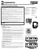
Figure 2 - Rear View of Enclosure
with mounting hole dimensions
6-1/8”
2-1/2”
• Jumper wires are not included.
• Alterations or modifications to the device will void warranty.
GM40AVE-RD89 TERMINAL DESIGNATIONS
NO 2NC 2NONCL 2/NL 1
T
TIMER
L N
COM
LOAD
#1
LOAD
#2
COM2
120/277 VAC Application Two Loads
COM2NO 2NC 2NONCL 2/NL 1
T
TIMER
L1 L2
COM
LOAD
#1
208/240 VAC Application One Load
NO Contacts:
40 A Resistive, 120-277 VAC
30 A Ballast, 120 VAC
20 A Ballast, 277 VAC
15 A Tungsten, 120 VAC
300 VA Pilot Duty, 120-240VAC
1 HP, 16 FLA, 90 LRA @ 120 VAC
2 HP, 12 FLA, 52 LRA @ 208-277 VAC
NC Contacts:
30 A Resistive, 120-277 VAC
10 A Ballast, 277 VAC
2 A Tungsten, 120 VAC
1 HP, 12 FLA, 30 LRA @ 120 VAC
2 HP, 10 FLA, 30 LRA @ 240 VAC
ELECTRICAL RATINGS
Risk of Fire or Electric Shock
GM40AVE-RD89 Digital timer controls
INSTALLATION INSTRUCTIONS
1. Open door and remove the interior protective cover by releasing the spring latch. (See Figure 1)
2. Remove the printed circuit board by releasing the spring latch holding the bottom of the board.
(See Figure 1)
3. Select knockouts to be used. Remove the inner 1/2" knockout by inserting a athead screwdriver
in the slot and carefully punch the knockout loose. Remove slug. If 3/4" knockout is required,
remove the outer ring with pliers after removing the 1/2" knockout. Smooth edge with knife, if
necessary.
4. Place the enclosure in the desired mounting location, and mark the three mounting holes (refer to
Figure 2 for dimensions). Install the top screw rst with one of the supplied spacers, and then hang
the enclosure by the keyhole. Drive the remaining two screws at the bottom of the enclosure
through the mounting holes while passing each screw through one of the supplied spacers and in
to the wall.
5. Connect conduit hubs to conduit before connecting the hubs to the enclosure. After inserting hubs
into enclosure, carefully tighten hub lock nut. Do not over-torque.
6. Replace printed circuit board making sure to engage spring latch at the bottom of PCB.
7. Wire in accordance with national and local electrical and safety codes (see wiring diagrams).
8. Grounding: Terminate all ground wires to the ground lug inside the case at the bottom of the
enclosure.
9. Replace interior protective cover.
10. Close the enclosure door.
PROGRAMMING INSTRUCTIONS
The installer should refer to the supplemental instruction manual included with this unit for information
regarding setting the time, symbols, keys and programming.
AC voltage must be present at terminals L1 and L2/N for the relays to operate and the status indicator
to change from ON to OFF.
APPLICATION
The GM40AVE-RD89 Time Controls are universal, electronic time switches designed for general
purpose commercial applications. The control operates on any AC voltage from 120 VAC to 277 VAC.
The mechanism is mounted in an indoor/outdoor enclosure and has been designed for the control of
lighting, heating, air conditioning, pumps, motors, or general electrical circuits in residential,
commercial, industrial and agricultural facilities.
Interior Protective Cover
Figure 1 - Spring Latch
Timer Mechanism
WARNING
NOTICE
Read instructions completely before installation and retain this booklet for future reference.