
Installation Manual

IMPORTANT SAFETY INSTRUCTIONS • SAVE THESE INSTRUCTIONS
INSTALLATION INSTRUCTIONS
IG2240-IMSK
TYPE 1 AND 2 SURGE PROTECTIVE DEVICES
APPLICATION NOTES
1. Thoroughly read instructions before installing SPD unit.
2. This product is designed to protect against momentary transient overvoltage events.
3. This product may not protect against nearby lightning strikes.
4. This device features internal protection that will disconnect the surge protective component at the end of its useful life but will maintain power to the load-now unprotected. If this situation is undesirable
for the application, follow the manufacturers instructions for replacing IModule™ units.
5. Observe warnings and instructions on front panel and unit label of product.
DEFINITIONS
Type 1 SPD: A typical type 1 SPD installation will be connected between the secondary of the service transformer and the line side of the service panel. This installation is intended to be installed without
overcurrent protection to the SPD.
Type 2 SPD: A typical type 2 SPD installation will be connected to the load side of the service panel and is intended to be installed with overcurrent protection to the SPD.
INSTALLATION:
1. Verify system voltage.
2. Make sure SPD is correctly rated for your system.
3. Determine mounting location of SPD unit.
The SPD unit should be located as close as possible to the load to be protected to minimize all wire lengths.
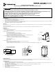
4. Mount enclosure
- Remove dead front from SPD unit.
- Disconnect power to unit at power source before installation.
- Remove needed knockout from SPD unit once wire routing has been determined.
- Only one conduit connection may be made to SPD unit enclosure.
- Mount enclosure using suitable fasteners in locations shown below. Do not rely on conduit fitting to support SPD.
5. Follow wiring diagram for all connections (Located within instruction sheet and SPD unit).
- Lead lengths can be replaced at terminal; splicing of leads is not recommended.
- Cut all wires to a minimum suitable length while maintaining a 4” recommended bend radius.
- Do not coil excess wire.
- Make sure all connections are secure.
- Replace dead front.
6. Energize SPD unit
- Flip circuit breaker (when used) to ON position at main service panel or disconnect switch(es).
- Flip Module Power Switch within SPD unit to on position.
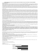
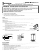
- Indicators: Each IModule™ has a blue LED to indicate the SPD unit has power and a green LED to indicate that the IModule™ is providing protection.
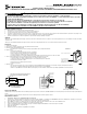
*C/B
GND (green)
Neutral (white)
Line (black)
Line (black)
SPD TYPE 1 AND 2 WIRING DIAGRAM
120/240 VAC SINGLE-PHASE
SPD
*2 Pole 30 A circuit breaker in Service Panel.
(Not required for SPD type 1 installations)
2 1/2"
5"
1 5/8"
3/4" 3/4"
1 5/8"
10 3/8"
Metal indoor enclosure
(Flush mount kit IG2200--FMK)
SERVICING INSTRUCTIONS:
The IModule™will absorb the energy of the surges to protect the connected load. If the green LED is OFF, the IModule™ is no longer providing protection and should be replaced as soon as possible.
All three of the removable IModule™ units must be replaced every three years to maintain the connected equipment warranty.
TO REPLACE IModule™:
1. POWER MUST BE REMOVED FROM THE IModule™ UNITS BEFORE REPLACING.
2. Move the Module Power Switch within the SPD to the OFF position. This will ONLY remove power to the IModule™ units. This switch does not remove power to the protected load. This switch is not used
as an overcurrent protection device (OCPD).
3. Remove IModule™ to be replaced by firmly pulling straight out from SPD unit. The module door within the unit will close once the IModule™ is removed.
4. Make sure IModule™ is correctly rated for system.
5. Place new IModule™ back into SPD unit. Make sure IModule™ alignment key is oriented correctly when inserting.
6. Make sure the IModule™ is fully seated.
7. Re-energize SPD unit.
8. Verify the blue and green LED’s within each IModule™ are lit.
SPD
UNIT
Main Breaker
2-Pole, 30A circuit
breaker
Green (Ground)
Type 2 Installation
Black (Line)
Black (Line)
Neutral (White)
Blue LED: Power indicator
Green LED: Status indicator
Alignment key of module
ON: Protection is being provided.
OFF: IModule™ is no longer providing
protection. Replace IModule™ as soon
as possible.
IModule™
Risk of Fire or Electric Shock
• Disconnect power at the circuit breaker(s) or disconnect switch(es) before installing or servicing.
• Turn Module Power Switch to the OFF position, (if provided), or remove power at the power source before replacing IModule™ units.
• Confirm Smart Guard ™ is rated for the correct voltage per part number specified on your SPD enclosure.
• Installation and/or wiring must be in accordance with national and local electrical code requirements.
• Installation and service to be performed by a qualified licensed technician or electrician.
• Bonding between conduit connections is not automatic and must be provided as part of the installation.
• KEEP DOOR CLOSED AT ALL TIMES when not servicing.
WARNING