
Installation Guide

DESCRIPTION:
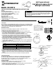
The IOS-CMP-U 360° Passive Infrared (PIR) Line Voltage Occupancy Sensors control lighting systems
based on occupancy and ambient light levels. When movement is detected, the sensor turns the lights
ON. If no movement is detected for a user-specified time, the lights are turned OFF. The occupancy
sensor provides a 360° coverage pattern, up to 1200 square feet.
MOUNTING THE SENSOR
NOTE: A junction box and Phillips screwdriver are needed to complete this procedure.
1. Make sure power is turned off at the main disconnect.
2. Remove the screws on the occupancy sensor cover and remove the cover from the sensor.
3. Observe these guidelines when mounting the sensor:
• The occupancy coverage area may be more or less than the sensing distances shown in Figure 1
due to potential coverage area obstacles, such as furniture or partitions.
• Place the sensor 4 to 6 feet away from air supply ducts to prevent false activations.
• If you mount the sensor outside of 8 to 10 feet from the floor, it affects the coverage pattern.
• Decreasing the mounting height decreases the sensor range and increases the sensitivity to
smaller motions. Mounting the sensor at heights more than 12 to 14 feet reduces sensitivity
• Each occupant should be able to clearly view the sensor to guarantee no obstruction in the area
• Avoid placing the sensor directly in line with an open door through which it has a clear view out.
This may cause the sensor to detect people walking by the door.
• To obtain complete coverage in large areas, install multiple sensors to create an overlap with each
adjacent sensor’s coverage area.
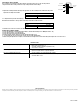
4. Connect high voltage wires to the appropriate terminals on the sensor. See the table below and
Figure 4.
Connect To
Hot wire of main power Black wire on the sensor
Load wire Red wire on the sensor
Neutral wire to load and main power White wire on the sensor
Gray wires (if applicable) Terminals on the momentary switch
5. Loosen the mounting screws attached to the junction box.
6. Align the sensor the mounting screws in the box over the keyholes on the sensor’s rear housing.
7. Push the sensor into the junction box and align the mounting screws on the junction box with the
keyhole slots on the sensor so that the screws are seated in the keyhole slots. Tighten mounting
screws.
8. Re-install the front cover on the sensor and secure with the screws previously removed.
ADJUST THE LIGHT LEVEL
The Light Level feature enables the user to adjust the level of light needed to be detected before
the sensor turns lighting ON. Remove the cover from the sensor and adjust the lighting from
the light level dial on the sensor (see Figure 5). You can set the dial anywhere between + or – to
obtain the optimal brightness configuration for the room (see Figure 3).
SENSOR ADJUSTMENT
Follow this procedure to verify the sensor coverage and customize the settings.
1. Remove the screws on the front cover and remove the cover.
2. Make sure all the furniture in the sensing area is installed, the lighting circuits are turned on and
the HVAC systems are in the Override position.
3. If there is a VAV (Variable Air Volume) system, set it to the highest airflow.
360˚ Passive Infrared
Line Voltage Occupancy Sensor
With Light Level Feature
MODEL: IOS-CMP-U
Ratings:
Input Voltage: 120/277 VAC, 60 Hz
Electronic Ballast (LED): 800 VA, 120 VAC; 1600 VA, 277 VAC
Tungsten (Incandescent): 800 W, 120 VAC
Fluorescent / Ballast: 800 VA, 120 VAC; 1600 VA, 277 VAC
Resistive (Heater): 10 A, 120 VAC
Motor: 1/4 HP, 120 VAC
Adjustable Light Level – 10 fc - 150 fc
Adjustable Time Delay - 15 sec - 30 min
Sensitivity Adjustment - 50% or 100% (DIP switch 1)
Coverage - Up to 1200 ft
2
Figure 3
Figure 2
Figure 4
Figure 5
IOS-CMP-U
- +
Light
- +
Light
- +
Light
- +
Light
- +
Light
- +
Light
Risk of Fire, Electrical Shock or Personal Injury
• Turn OFF power at circuit breaker or fuse and test that the power is OFF before wiring.
• To be installed and/or used in accordance with appropriate electrical codes and regulations.
• If you are not sure about any part of these instructions, consult a qualified electrician.
• Use this device only with copper or copper clad wire.
• INDOOR USE ONLY
WARNING
44 ft
13.4m
8 ft
tf 22tf 22 tf 31tf 31 7 ft 7 ft3 ft 0 3 ft
Typical
desk-top
level
Figure 1
Front Cover
Rear Housing
Wire
Screws
4"Octagonal box 2-1/2"
deep mounting
Drop Ceiling
PIR lens
PIR Activity LED(Red)
Light level Adjustment
Double gang mudring
mounting holes
DIP switches
Keyhole slots(for mounting to
4" octagonal box)
TEST
10
Min
20
Min
30
Min
Time Delay Adjustment
-
+
Light
INSTALLATION AND CONFIGURATION INSTRUCTIONS
(Hot)
(Load)
(Neutral)
Black
Red
White
Grey1
Grey2
33
Figure 6
Figure 7