
Instructions / Assembly
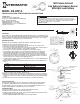

DESCRIPTION:
The IOS-CMP-U 360° Passive Infrared (PIR) Line Voltage Occupancy Sensors control lighting systems
based on occupancy and ambient light levels. When movement is detected, the sensor turns the lights
ON. If no movement is detected for a user-specified time, the lights are turned OFF. The occupancy
sensor provides a 360° coverage pattern, up to 1200 square feet.
MOUNTING THE SENSOR
NOTE: A junction box and Phillips screwdriver are needed to complete this procedure.
1. Make sure power is turned off at the main disconnect.
2. Remove the screws on the occupancy sensor cover and remove the cover from the sensor.
3. Observe these guidelines when mounting the sensor:
• TheoccupancycoverageareamaybemoreorlessthanthesensingdistancesshowninFigure1
due to potential coverage area obstacles, such as furniture or partitions.
• Placethesensor4to6feetawayfromairsupplyductstopreventfalseactivations.
• Ifyoumountthesensoroutsideof8to10feetfromtheoor,itaffectsthecoveragepattern.
• Decreasingthemountingheightdecreasesthesensorrangeandincreasesthesensitivityto
smallermotions.Mountingthesensoratheightsmorethan12to14feetreducessensitivity
• Eachoccupantshouldbeabletoclearlyviewthesensortoguaranteenoobstructioninthearea
• Avoidplacingthesensordirectlyinlinewithanopendoorthroughwhichithasaclearviewout.
This may cause the sensor to detect people walking by the door.
• Toobtaincompletecoverageinlargeareas,installmultiplesensorstocreateanoverlapwitheach
adjacent sensor’s coverage area.
4.Connecthighvoltagewirestotheappropriateterminalsonthesensor.Seethetablebelowand
Figure4.
Connect To
Hot wire of main power Black wire on the sensor
Load wire Red wire on the sensor
Neutral wire to load and main power White wire on the sensor
Gray wires (if applicable) Terminals on the momentary switch
5. Loosen the mounting screws attached to the junction box.
6. Align the sensor the mounting screws in the box over the keyholes on the sensor’s rear housing.
7. Push the sensor into the junction box and align the mounting screws on the junction box with the
keyhole slots on the sensor so that the screws are seated in the keyhole slots. Tighten mounting
screws.
8.Re-installthefrontcoveronthesensorandsecurewiththescrewspreviouslyremoved.
ADJUST THE LIGHT LEVEL
The Light Level feature enables the user to adjust the level of light needed to be detected before
the sensor turns lighting ON. Remove the cover from the sensor and adjust the lighting from
the light level dial on the sensor (see Figure 5). You can set the dial anywhere between + or – to
obtain the optimal brightness configuration for the room (see Figure 3).
SENSOR ADJUSTMENT
Follow this procedure to verify the sensor coverage and customize the settings.
1. Remove the screws on the front cover and remove the cover.
2. Make sure all the furniture in the sensing area is installed, the lighting circuits are turned on and
the HVAC systems are in the Override position.
3. IfthereisaVAV(VariableAirVolume)system,setittothehighestairow.
360˚ Passive Infrared
Line Voltage Occupancy Sensor
With Light Level Feature
MODEL: IOS-CMP-U
Specifications:
Incandescent - 800W-120VAC,60HZ
Fluorescent-800VA-120VAC/1600VA-277VAC,60HZ
Motor-1/4HP,120VAC,60HZ
Adjustable Light Level - 10FC-150FC
AdjustableTimeDelay-15sec.-30min
SensitivityAdjustment-50%or100%(DIPswitch1)
Coverage - Up to 1200 ft
2
Figure 3
Figure 2
Figure 4
Figure 5
IOS-CMP-U
- +
Light
- +
Light
- +
Light
- +
Light
- +
Light
- +
Light
Risk of Fire, Electrical Shock or Personal Injury
• TurnOFFpoweratcircuitbreakerorfuseandtestthatthepowerisOFFbeforewiring.
• Tobeinstalledand/orusedinaccordancewithappropriateelectricalcodesandregulations.
• Ifyouarenotsureaboutanypartoftheseinstructions,consultaqualiedelectrician.
• Usethisdeviceonlywithcopperorcoppercladwire.
• INDOORUSEONLY
WARNING
44 ft
13.4m
8 ft
tf 22tf 22 tf 31tf 31 7 ft 7 ft3 ft 0 3 ft
Typical
desk-top
level
Figure 1
Front Cover
Rear Housing
Wire
Screws
4"Octagonal box 2-1/2"
deep mounting
Drop Ceiling
PIR lens
PIR Activity LED(Red)
Light level Adjustment
Double gang mudring
mounting holes
DIP switches
Keyhole slots(for mounting to
4" octagonal box)
TEST
10
Min
20
Min
30
Min
Time Delay Adjustment
-
+
Light
INSTALLATION AND CONFIGURATION INSTRUCTIONS
(Hot)
(Load)
(Neutral)
Black
Red
White
Grey1
Grey2
33
Figure 6
Figure 7