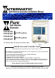
PE25K120V PE25K240V 25,000 gallons PE40K120V PE40K240V 40,000 gallons The Natural Way To Purify Your Pool or Spa IMPORTANT SAFETY INSTRUCTIONS This manual must be given to the homeowner to ensure warranty coverage. When installing and operating this Product and other associated equipment, basic safety precautions should always be followed, including the following: 1. DO NOT OPEN THE GENERATOR BOX – NOT A SERVICABLE UNIT 2. READ AND FOLLOW ALL INSTRUCTIONS 3. Disconnect all AC power before installation.
Table Of Contents Section 1. General Information...........................................................................1 Section 2. Important Safety Information ............................................................1 Section 3. Installation Instructions......................................................................2 3.1 General Information .................................................................2 3.2 Plumbing Your System ........................................................
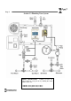
Page 1 Section 1. General Information Congratulations on the purchase of your new Salt Chlorine Generator. Your purchase will minimize the efforts needed to maintain your pool and maximize your enjoyment for many years. Before installation or operation, please read these instructions carefully. This manual contains easy to follow step-by-step procedures to properly install and operate your system.
Page 2 CAUTION In Canada and some other regions, local codes require the unit be connected only to a circuit that is protected by a ground-fault circuit-interrupter (GFCI). The installer should provide this GFCI requirement. The GFCI should be tested on a regular basis by pushing the test button. If the GFCI fails to operate correctly, there is ground current flowing indicating the possibility of an electric shock. Do not use this unit.
Page 3 Section 3.
Page 4 Section 3.3 Installing the Cell NOTE Lay out equipment pieces to be sure there is enough pipe space between the last piece of apparatus and the tees in the return line to fit the Flow Sensor and the Cell. A Vertical Installation may be used to save space. 1. The Cell and Flow Sensor must be installed downstream from the filter and heating devices but before any tees in the return line.
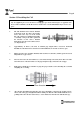
Page 5 Section 3.4 Installing the Flow Sensor Flow direction 1. Install the Flow Sensor between the last piece of apparatus and the Cell (if installed after the Cell, damage to the sensor may result). When possible, install on a horizontal pipe. 2. Mark two lines on the pipe 3 inches (~76 mm) apart and cut with a hacksaw or pipe cutters. 3. Clean and glue the “T” connector (included) to the pipe making sure that the threaded end with the sensor is on the topside of the pipe. 4.
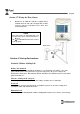
Page 6 Section 3.5 Mounting the Control Box (Continued) 2. The Control Box must be mounted vertically on a flat surface and a minimum of 5 ft (1.5m) horizontal distance (or more, if local codes require) from the pool/spa. 3. Locate a position for your Control Box within 10 ft (~3 meters) of where the Cell will be installed and within 2 ft of the power supply to ensure enough wire is available. 4.
Page 7 Section 3.6 Wiring the Control Box CAUTION Check whether your chlorine generator operates on 120 volts or 240 volts (see label on the left side of the Control Box), and be sure to wire the system accordingly. It is critical to wire the chlorine generator in such a way that it can only operate when the pump is operating (i.e. load side). See instructions below for details. 1. Attach the green ground wire to the grounding lug or bar. 2.
Page 8 Section 3.7 Wiring the Flow Sensor 1. Find the two 18 AWG wires with the ¼” Quick connect terminals from the Cell cable and push them on their respective connectors on the Flow Sensor. These wires are interchangeable. NOTE Flow Sensor wires are interchangeable. You must have flow sensor connected in order for the Salt Chlorine Generator system to work properly. Flow Sensor Section 4. Startup Instructions Section 4.
Page 9 Section 4.2 Adding Salt 1. Determine how much salt is needed from the Salinity Demand Table on the following page. This table is based on a salt concentration of 3500 ppm (approximately 1/3 of 1%). More may be added for larger pools (e.g. 4000 ppm) and less for very small bodies of water. 2. Keep the pump on to circulate the water. 3. Distribute the determined amount of salt evenly around the pool.
Page 10 Section 4.4 Salinity Demand Table (in lbs.
Page 11 Section 5. Operating Instructions Section 5.1 Chlorinator Specifics This product is an automatic Natural Chlorine Generator for pool and/or spa sanitation. It is the workhorse of chlorine generators. The system uses a very low concentration of salt, less than the concentration in a human teardrop, and converts it into free chlorine that kills algae and bacteria in your pool. After killing the algae and bacteria, the chlorine reverts back into sodium chloride.
Page 12 To generate more chlorine 1. 2. 3. 4. 5. Turn the Control Knob to a higher setting as necessary, 10% to 100% chlorine production level. (See “Power Meter” in the next section) Ensure sufficient run time (at least 8 hours / 1 ½ turnovers). Ensure salt level is correct and the Cell is clean (see “Salinity Indicator” in the next section). Ensure proper water balance including pH and stabilizer levels (see “Understanding the Chemistry” for recommended levels). Point pool jets down and to the side.
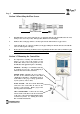
Page 13 Section 5.7 Controls Red Light - Above the Power Meter indicates that the salt level in the pool is on the high side. This does not harm the Natural Generator, but is provided as a cautionary notice to the user not to add more salt to the pool. Operation at very high levels (i.e. above 5500ppm) is not recommended. Slowly turn down the Control Knob until the desired Power Meter light illuminates (i.e. desired chlorine production level).
Page 14 Salinity Indicator -- To check the salt level, turn the Control Knob clockwise to full power and check the light reading. 100% reading indicates that the salt level is sufficient. Return the Control Knob to the desired chlorine production setting depending on the chlorine level in your pool (10% to 100% production rate). Red Light - above the Power Meter indicates that the salt level in the pool is on the high side.
Page 15 Section 6. Maintenance/Cleaning Maintaining your I-Pure System requires minimal work but will maximize the performance and life of the system. NOTE: Pool water should be tested bi-monthly. Section 6.1 Cell Maintenance Our clear Cell allows for easy regular inspections for calcium build up. Visually check the Cell periodically, and clean it as necessary (1 to 2 times per year).
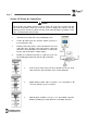
Page 16 Cleaning With Optional Cleaning Cap (continued) 4. 5. 6. 7. 8. 9. Pour into cell, either undiluted white distilled vinegar, or a solution of diluted muriatic acid (5 parts water to 1 part muriatic acid). (Fig. 3) Wait for foaming to stop (5-10 minutes). If muriatic acid was used, safely dispose of it by pouring it into your pool. Rinse cell with water hose. Put the O-ring back in place and re-install the Cell in the line.
Page 17 Section 6.3 Understanding The Chemistry Below is a table showing the recommended balance levels followed by a more detailed explanation of the factors affecting water chemistry. Maintaining these levels will prevent corrosion and scaling and will ensure maximum enjoyment of the pool. You should test your water periodically. If the water chemistry needs adjustment, your authorized dealer or most pool stores can supply you with the appropriate chemicals and procedures.
Page 18 Section 6.3 Understanding The Chemistry (continued) PH is a measure of how acidic or basic a solution is. A scale of 0 to 14 is used to measure pH. Pure water has a pH of 7 (neutral), acid solutions have a pH of less than 7, and basic (alkali) solutions have a pH of more than 7. The recommended range is 7.2 to 7.6; chlorine is more effective within this range and the water is most comfortable for bathers. Water with very high pH levels can cause scaling in the pool, on the walls and in pipes.
Page 19 Section 6.4 Calculating Saturation Index Test the water for pH, Alkalinity, Calcium Hardness, and Temperature, then follow the simple steps below: 1. Write your pools pH level here: pH ________ 2. Find your Alkalinity level in the chart below, and write the corresponding Alkalinity Factor here: Alkalinity Factor ________ Pool Alkalinity Factor 3. 50 1.7 75 1.9 100 2.0 150 2.2 200 2.3 300 2.5 400 2.6 5 0.3 25 1 50 1.3 75 1.5 100 1.6 150 1.8 200 1.9 300 2.1 400 2.
Page 20 Section 7. Troubleshooting Evaluating the possible causes for each problem from top to bottom (first to last) will avoid any extra labor. ¾ 1. Chlorine Level Low Low Salinity ¾ Pump operation time too short ¾ Low Stabilizer (Cyanuric Acid) 2. Green Pool 3. On/Off Light is OFF: No power ¾ Chemical Imbalance ¾ Chlorine level too low. ¾ System is turned off. ¾ Main fuse blew. ¾ Breaker jumped Check the salinity level. (See “Salinity Indicator” section).
Page 21 Section 7. Troubleshooting (continued) PROBLEM POSSIBLE CAUSES ¾ Insufficient water flow from pump to Flow Sensor and Cell. 7. Flow Light is Solid Red ¾ Obstruction or scale buildup in Cell. ¾ Flow Sensor was not installed in the correct direction. ¾ Flow Sensor is not fully threaded into the “T” connector. ¾ Cut wires or insufficient wire connections. WHAT TO DO ¾ This is normal for a few minutes at initial startup or if air is in the lines. ¾ Clean filters and strainers.
Page 22 Section 7. Troubleshooting (continued) PROBLEM 10. Salinity High POSSIBLE CAUSES WHAT TO DO ¾ This does no harm to the Natural Generator, but simply indicates that the salt level is on the high side for your information. Slowly turn down the Control Knob ¾ Salinity High. Enough salt (counterclockwise) until the desired Power has been added causing the Meter light illuminates. red light above the power meter ¾ It is also recommended to periodically to light. test the salt level by a professional.
Page 23 13. Power Meter not responding, but On/Off light is on 14. Scale build-up inside Cell ¾ Control Knob s et too low ¾ Im proper s alt level. The s ys tem autom atically s huts down the Power Meter when the s alt level is extrem ely low or extrem ely high. ¾ Standard occurrence that needs to be cleaned approxim ately twice/year. ¾ 15. White flakes in the water 16. Cloudy water 17. Colored Water 18. Algae Chem ical im balance. ¾ Norm al occurrence when Cell cleans its elf.
Warranty Registration Cell Serial # ______________________ Control Box Serial # ______________(On the side of the control box mounted to the wall) ------------------------------------------------------------------------------- --------------------------------------------------------------------------------OWNER’S REGISTRATION FORM 1-YEAR LIMITED WARRANTY Owner’s Name___________________________________________Signature____________________________________________ Street Address_____________________________