
User's Manual


Three: PE653 Receiving Device Installation 37
Providing a brighter solution.™
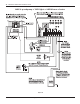
The actuators must be installed to automatically rotate your valves between the pool and spa
plumbing. The 24 VAC power for the Valve Actuators is produced by a transformer in the
P4243ME. All power to both units must be turned OFF when connecting the black and white
actuator control leads to the PE653 (see diagram above). Refer to the installation and wiring
directions for the P4243ME Actuator Control and PE24VA Actuators for additional instructions
for each unit. Remove power from the P4243ME and the Multi-Wave Receiving Device.
Attach the valve actuators (PE24VA) to the water valves. (See instructions included with 1.
actuators).
Run the actuator cable(s) to the P4243ME control through the low voltage raceway.2.
Remove the access door at the top right of the P4243ME mechanism. 3.
Insert the three-pin connector of the motorized valve actuator to any of the three available 4.
connectors on the P4243ME circuit board.
Connect 120 or 240 VAC power leads to the correct colored wires of the P4243ME 5.
transformer (see above).
Connect the two Actuator Control wire leads as shown above in Figure 3-25.6.
Apply power to both the PE653 and the P4243ME and synchronize the actuators as follows:7.
Make sure that circuit number 4 is OFF (Green Load ON indicator is OFF). This indicates a.
that the switch is in POOL mode.
If either of the Actuators is positioned backwards, flip the switch on the back to reverse b.
position.
Turn circuit number 4 ON (Green Load ON indicator is ON). This indicates that the switch c.
is in SPA mode.
Verify that the Actuators are correctly synchronized with your installation.d.
Fireman’s Switch Connection
The Intermatic Multi-Wave Control System is capable of controlling most heaters or heat pumps
in the market today. Circuit number 5 in the PE653 is configured to control the heater using the
24 VAC thermostatic circuitry. Locate your type of heater in the following pages and follow the
instructions for proper installation.
Refer to the heater manufacturer’s installation and wiring manual if you do not find information
regarding your specific brand or model of heater.
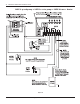
Connection for Jandy Heaters
(Jandy HiE2 shown)
Connect two #14 gauge wires, designed for 1.
use in hot environments to terminals 8 & 9
on the PE653 and route them through the
low voltage knockout.
Make sure that the low voltage divider is 2.
securely installed.
Figure 3-26 Typical Jandy heater wiring connection