
Instructions / Assembly
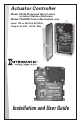

This Switching Device is most suited for controlling the shared equipment of Pool-Spa
combinations but it can be also used to control all the equipment typically needed in con-
nection with water features, water gardening solar heating and other similar applications.
The Mechanism is designed to “snap” into most Intermatic panels and outdoor
enclosures in use today and it can be interfaced with other Intermatic products in order
to facilitate a large number of custom applications.
DANGER
WARNING
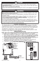
WIRING INSTRUCTIONS
• Do not permit small children to operate or use the Pool/Spa unless they are closely
supervised at all times.
• Test GROUND FAULT protection regularly. If it fails to reset, DO NOT USE THE POOL or
SPA! Contact a qualied service technician.
• Always disconnect electricity before servicing this Control or the equipment connected to
it.
When installing and operating this Product and other associated equipment, basic safety
precautions should always be followed,
• This Control must be installed by a qualied person, according to National and Local
Electrical Codes.
• Install this Control no less than 5 feet (3 meters in Canada) from inside edge of pool.
USE COPPER CONDUCTORS ONLY rated 75˚C minimum.
• Do not exceed the maximum ratings of individual components, wiring devices, and
current carrying capacity of conductors.
• For Control grounding, bonding, installing and the wiring of underwater lights, refer to
Article 680 of the National Electrical Code or Article 68 of the Canadian Electrical Code.
• The Control should not operate any equipment which could cause bodily injury or
property damage should it be activated unexpectedly.
GENERAL INFORMATION
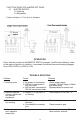
Figure 3
1 2 3
VALVE ACTUATOR
CONNECTIONS
1 2
3
SPA
(HIGH)
POOL
(LOW)
COM
HEATER
CONNECTIONS
(SEE FIG. 2)
WIRED
REMOTE
WIRED
REMOTE
FUNCTION
SELECTOR
JUMPERS
SEE NOTE 1
J1
J2
J3
J4
1 2 3
TERMINAL
SCREWS
2
NOTE: High and low voltage wires should not occupy the same conduits and compartments.
If needed, install corrugated tubing kit, Part No. 156PA12976A rst (not supplied).
1. Make power connections to Transformer. If 120 Volt, connect supply to BLK and WHT
leads, if 240 Volt, connect supply to BLK and RED leads. Insulate (cap) unused lead.
2. Plug Motorized Valve Acutator(s) into any polarized receptacle(s) see drawing.
3. Connect any external REMOTE SWITCH to the two Black and White striped leads as
shown below and apply the Trigger Voltage of either 120 or 240VAC.
4. If applicable, make heater connections. Remove terminal block from socket and
depending on the type of heater, follow one of the diagrams on page 3.
5. If applicable, make Remote Control connection to the 8 pin polarized receptacle.
LOW VOLTAGE COMPARTMENT
VALVE
ACTUATORS
HEATER
TERMINALS
JUMPERS
REMOTE
CONTROL
CONNECTOR
REMOTE
SWITCH
TRANSFR.
RED
WHT
BLK
BLK/WHT
POWER INPUT
SEE INSTRUCTION #1
BLK/WHT
TRIGGER
VOLTAGE
SEE
INSTRUCTION #3