
Instructions / Assembly

WP1000MX SERIES
WEATHERPROOF RECEPTACLE COVERS
FOR EXTRA-DUTY APPLICATIONS
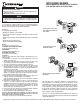
Single-gang horizontal
Model WP1010HMXD
Single-gang vertical Model
WP1010MXD, WP1250MVXD and
WP3110MXD
A grounding wire is provided for all models. The mounting screw that holds the receptacle or light switch should pass through the ring terminal on the end of the wire.
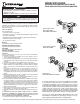
Double-gang Model WP1030MXD and
WP1250MXD
This double-gang cover is designed for installation on double-gang junction
boxes. If installing on a non-metallic junction box, you will need to use the
grounding wire (as shown on the Optional Grounding illustration). If the junction
box is non-metallic, a separate ground will need to be run and connected to
the grounding wire by cutting and removing the spade terminal, stripping
the ground wire and making a pigtail connection. Also note for single-gang
installation you will need to purchase an Intermatic insert model #WP101 for
duplex receptacle or WP102 for GFCI application.
The insert for model WP1030MXD and WP1250MXD may be oriented for
horizontally or vertically mounted receptacles and is designed for double duplex
or double GFCI applications.
This die cast cover can be used outdoors or in other wet locations when cover
is closed (protects receptacles while in-use for unattended applications).
The cover is UL Listed, CSA certified, rated Type 3R and meets 2014 National
Electrical Code requirements covered by Article 406.9 (B)(1).
Contents
The following items are included:
• Weatherproof cover/base - pre-assembled.
• Universal insert for duplex receptacles (model WP1030 includes a double
duplex insert)
• Universal insert for GFCI receptacles (model WP1030 includes a double GFCI
insert)
• Gasket with slits for mounting screws
• Baggie assembly with mounting hardware
Models
The instructions cover these models:
WP1010MXD, WP1250MVXD, WP3110MXD
Single-gang vertical mounting only
WP1010HMXD
Single-gang horizontal mounting only
WP1030MXD, WP1250MXD
double-gang, 2 device installation
Installation
Follow the steps listed below, while referring to the illustrations for your
particular model.
1. If installation is being done on an existing receptacle(s), remove the
existing cover and discard.
2. The mounting screws that hold the receptacle or GFCI to the junction box
can be removed. Do not remove the receptacle wiring connections.
3. Select the correct insert for your application and press into base.
4. Locate the gasket as required for the installation. The gasket can be
temporarily held to the back of the base/insert assembly using the
mounting hardware provided. The receptacle cover should be installed on a
smooth, flat, non-porous surface.
To ensure a weatherproof seal on irregular surfaces such as brick or cedar
siding, a 1/4" bead of non-hardening silicon caulk compound (neoprene,
urethane or polyurethane type) should be placed between the weather-
proof receptacle gasket and the mounting surface.
5. Mount the base/insert assembly and the receptacle(s) to the junction box
using two of the long screws provided (do not over-tighten).
To ensure weatherproof protection, the cover must be installed so that the
hinge points are located at the top.
6. If mounting to an outdoor junction box or FS box, use the remaining long
screws, 2 or 4 screws as required, to further secure the cover and insert
assembly to the junction box. Note that holes are located in the insert for
mounting to an FS box or any standard single-gang box. For specially
designed junction boxes, holes should be carefully drilled to line up with
the holes in the box to accommodate mounting.
7. Be sure all screws are secure but not over-tightened. Install the remaining
1 or 2 short screws into the receptacle(s) as required.
8. A hasp is provided to allow for padlocking the cover if desired.
FOR BEST PROTECTION FROM RAIN OR HUMIDITY, BE SURE TO ROUTE THE
CORDS THROUGH THE CORD OUTLETS IN THE COVER AND PRESS THE COVER
FIRMLY UNTIL IT SNAPS CLOSED OVER THE HASP.
Cover may be removed for ease of mounting and then reattached.
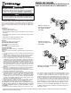
Optional Grounding
(Single gang
installation)
Optional
Grounding
WARNING
• Disconnect power at the circuit breaker(s) or disconnect switch(es) before
installing or servicing.
• KEEP COVER CLOSED when used in wet locations.
Risk of Fire or Electric Shock
NOTICE
• If using a power screwdriver, be careful not to over-tighten the screws
in the junction box and/or the electrical device to prevent stripping the
threads.