Exhibit L: User Manual - Part 2 of 2 FCC ID: HN2ABTM3-3
Chapter 6 — Scanner Support Code 128 Enumerations typedef enum tagCode128Decoding { ITC_CODE128_NOTACTIVE = 0, // Default ITC_CODE128_ACTIVE = 1, ITC_CODE128_NO_CHANGE = 255 } ITC_CODE128_DECODING; typedef enum tagEan128Identifier { ITC_EAN128_ID_REMOVE, ITC_EAN128_ID_INCLUDE, // Default ITC_EAN128_ID_NO_CHANGE = 255 } ITC_EAN128_IDENTIFIER; typedef enum tagCode128Cip128 { ITC_CODE128_CIP128_NOTACTIVE = 0, // Default ITC_CODE128_CIP128_ACTIVE = 1, ITC_CODE128_CIP128_NO_CHANGE = 255 } ITC_CODE128_CIP128; #d
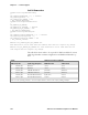
Chapter 6 — Scanner Support IS9CConfig::GetI2of5 This function retrieves the current settings of Interleaved 2 of 5. Syntax HRESULT IS9CConfig::GetI2of5( ITC_INTERLEAVED2OF5_DECODING* peDecode, ITC_INTERLEAVED2OF5_CHECK_DIGIT* peCheck, ITC_BARCODE_LENGTH_ID* peLengthId, BYTE rbgLengthBuff[], DWORD* pdwNumBytes ); Parameters peDecode [out] Pointer to the ITC_INTERLEAVED2OF5_DECODING location to receive the decoding for Interleaved 2 of 5 symbology.
Chapter 6 — Scanner Support IS9CConfig::SetI2of5 This function updates the Interleaved 2 of 5 settings with new values. Syntax HRESULT IS9CConfig::SetI2of5( ITC_INTERLEAVED2OF5_DECODING eDecode, ITC_INTERLEAVED2OF5_CHECK_DIGIT eCheck, ITC_BARCODE_LENGTH_ID eLengthId, BYTE rgbLengthBuff[], DWORD dwNumBytes ); Parameters eDecode [in] Identifies the decoding for Interleaved 2 of 5 symbology. eCheck [in] Identifies the check digit.
Chapter 6 — Scanner Support Interleaved 2 of 5 Enumerations typedef enum tagInterleaved2of5Decoding { ITC_INTERLEAVED2OF5_NOTACTIVE = 0, // Default ITC_INTERLEAVED2OF5_ACTIVE = 1, ITC_INTERLEAVED2OF5_NO_CHANGE = 255 } ITC_INTERLEAVED2OF5_DECODING; typedef enum tagInterleaved2of5CheckDigit { ITC_INTERLEAVED2OF5_CHECK_NOTUSED, // Default ITC_INTERLEAVED2OF5_CHECK_MOD10_XMIT, ITC_INTERLEAVED2OF5_CHECK_MOD10_NOTXMIT, ITC_INTERLEAVED2OF5_CHECK_FRENCH_CIP_XMIT, ITC_INTERLEAVED2OF5_CHECK_FRENCH_CIP_NOTXMIT, ITC_I
Chapter 6 — Scanner Support IS9CConfig::SetMatrix2of5 This function updates the Matrix 2 of 5 settings with new values. Syntax HRESULT IS9CConfig::SetMatrix2of5( ITC_MATRIX2OF5_DECODING eDecode, DWORD dwLength ); Parameters eDecode [in] Identifies the decoding for Matrix 2 of 5 symbology. dwLength [in] Identifies the bar code length. Return Values HRESULT that indicates success or failure. Remarks None. See Also None.
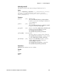
Chapter 6 — Scanner Support IS9CConfig::GetMSI This function retrieves the current MSI settings. Syntax HRESULT IS9CConfig::GetMSI( ITC_MSI_DECODING* peDecode, ITC_MSI_CHECK_DIGIT* peCheck, DWORD* pdwLength ); Parameters peDecode [out] peCheck [out] pdwLength [out] Pointer to the ITC_MSI_DECODING location to receive the decoding for MSI symbology. Pointer to the ITC_MSI_CHECK_DIGIT location to receive the check digit. Pointer to the DWORD location to receive the bar code length.
Chapter 6 — Scanner Support MSI Enumerations typedef enum tagMsiDecoding { ITC_MSI_NOTACTIVE = 0, // Default ITC_MSI_ACTIVE = 1, ITC_MSI_NO_CHANGE = 255 } ITC_MSI_DECODING; typedef enum tagMsiCheckDigit { ITC_MSI_CHECK_MOD10_XMIT, // Default ITC_MSI_CHECK_MOD10_NOTXMIT, ITC_MSI_CHECK_DOUBLEMOD10_XMIT, ITC_MSI_CHECK_DOUBLEMOD10_NOTXMIT, ITC_MSI_CHECK_NO_CHANGE = 255 } ITC_MSI_CHECK_DIGIT; #define ITC_BC_LENGTH_NO_CHANGE 255. This definition can be used when the bar code length does not require any change.
Chapter 6 — Scanner Support pePdfSender [out] pePdfAddressee [out] pePdfFileSize [out] pePdfChecksum [out] Pointer to the ITC_PDF417_SENDER location to receive the sender. Pointer to the ITC_PDF417_ADDRESSEE location to receive the addressee. Pointer to the ITC_PDF417_FILE_SIZE location to receive the file size. Pointer to the ITC_PDF417_CHECKSUM location to receive the checksum. Return Values HRESULT that indicates success or failure. Remarks None. See Also None.
Chapter 6 — Scanner Support Remarks None. See Also None.
Chapter 6 — Scanner Support ITC_PDF417_SEGMENT_COUNT_NO_CHANGE = 255 } ITC_PDF417_SEGMENT_COUNT; typedef enum tagPdf417TimeStamp { ITC_PDF417_TIME_STAMP_NOTXMIT = 0, // ITC_PDF417_TIME_STAMP_XMIT = 1, ITC_PDF417_TIME_STAMP_NO_CHANGE = 255 } ITC_PDF417_TIME_STAMP; typedef enum tagPdf417Sender { ITC_PDF417_SENDER_NOTXMIT = 0, // ITC_PDF417_SENDER_XMIT = 1, ITC_PDF417_SENDER_NO_CHANGE = 255 } ITC_PDF417_SENDER; typedef enum tagPdf417Addressee { ITC_PDF417_ADDRESSEE_NOTXMIT = 0, // ITC_PDF417_ADDRESSEE_XMIT =
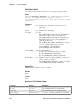
Chapter 6 — Scanner Support IS9CConfig::GetPlessey This function retrieves the current Plessey settings. Syntax HRESULT IS9CConfig::GetPlessey( ITC_PLESSEY_DECODING* peDecode, ITC_PLESSEY_CHECK_DIGIT* peCheck, DWORD* pdwLength ); Parameters peDecode [out] Pointer to the ITC_PLESSEY_DECODING location to receive the decoding for Plessey symbology. peCheck [out] Pointer to the ITC_PLESSEY_CHECK_DIGIT location to receive the check digit.
Chapter 6 — Scanner Support Plessey Default Settings Parameter Default Valid Range Decoding Not Active ITC_PLESSEY_DECODING Check Digit Not Transmitted ITC_PLESSEY_CHECK_DIGIT Bar Code Length Any Bar Code Length 0x00`0xFE ITC_BC_LENGTH_NO_CHANGE Plessey Enumerations typedef enum tagPlesseyDecoding { ITC_PLESSEY_NOTACTIVE = 0, // Default ITC_PLESSEY_ACTIVE = 1, ITC_PLESSEY_NO_CHANGE = 255 } ITC_PLESSEY_DECODING; typedef enum tagPlesseyCheckDigit { ITC_PLESSEY_CHECK_NOTXMIT = 0, // Default ITC_P
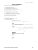
Chapter 6 — Scanner Support IS9CConfig::GetStandard2of5 This function retrieves the current Standard 2 of 5 settings. Syntax HRESULT IS9CConfig::GetStandard2of5( ITC_STANDARD2OF5_DECODING* peDecode, ITC_STANDARD2OF5_FORMAT* peFormat, ITC_STANDARD2OF5_CHECK_DIGIT* peCheck, ITC_BARCODE_LENGTH_ID* peLengthId, BYTE rgbLengthBuff, DWORD* pdwNumBytes ); Parameters peDecode [out] Pointer to the ITC_STANDARD2OF5_DECODING location to receive the decoding for Standard 2 of 5 symbology.
Chapter 6 — Scanner Support IS9CConfig::SetStandard2of5 This function updates the Standard 2 of 5 settings with new values. Syntax HRESULT IS9CConfig::SetStandard2of5( ITC_STANDARD2OF5_DECODING eDecode, ITC_STANDARD2OF5_FORMAT eFormat, ITC_STANDARD2OF5_CHECK_DIGIT eCheck, ITC_BARCODE_LENGTH_ID eLengthId, BYTE rgbLengthBuff[], DWORD dwNumBytes ); Parameters eDecode [in] Identifies the decoding for Standard 2 of 5 symbology. eFormat [in] Identifies the format.
Chapter 6 — Scanner Support Standard 2 of 5 Default Settings Parameter Default Valid Range Decoding Not Active ITC_STANDARD2OF5_DECODING Format Identicon (6 Start/Stop bars) ITC_STANDARD2OF5_FORMAT Check Digit Not Used ITC_STANDARD2OF5_CHECK_DIGIT Bar Code Length Minimum Length = 6 0x00-0xFE ITC_BC_LENGTH_NO_CHANGE Standard 2 of 5 Enumerations typedef enum tagStandard2of5Decoding { ITC_STANDARD2OF5_NOTACTIVE = 0, // Default ITC_STANDARD2OF5_ACTIVE = 1, ITC_STANDARD2OF5_NO_CHANGE = 255 } ITC_
Chapter 6 — Scanner Support IS9CConfig::GetTelepen This function retrieves the current Telepen settings. Syntax HRESULT IS9CConfig::GetTelepen( ITC_TELEPEN_DECODING* peDecode, ITC_TELEPEN_FORMAT* peFormat ); Parameters peDecode [out] peFormat [out] Pointer to the ITC_TELEPEN_DECODING location to receive the decoding for TELEPEN symbology. Pointer to the ITC_TELEPEN_FORMAT location to receive the format. Return Values HRESULT that indicates success or failure. Remarks None. See Also None.
Chapter 6 — Scanner Support Telepen Enumerations typedef enum tagTelepenDecoding { ITC_TELEPEN_NOTACTIVE = 0, // Default ITC_TELEPEN_ACTIVE = 1, ITC_TELEPEN_NO_CHANGE = 255 } ITC_TELEPEN_DECODING; typedef enum tagTelepenDecoding { ITC_TELEPEN_FORMAT_ASCII, // Default ITC_TELEPEN_FORMAT_NUMERIC, ITC_TELEPEN_FORMAT_NO_CHANGE = 255 } ITC_TELEPEN_FORMAT; IS9CConfig::GetUpcEan This function retrieves the current UPC/EAN settings.
Chapter 6 — Scanner Support upcACheck [out] Pointer to the ITC_UPCA_CHECK_DIGIT location to receive the UPC-A check digit. upcECheck [out] Pointer to the ITC_UPCE_CHECK_DIGIT location to receive the UPC-E check digit. ean8Check [out] Pointer to the ITC_EAN8_CHECK_DIGIT location to receive the EAN-8 check digit. ean13Check [out] Pointer to the ITC_EAN13_CHECK_DIGIT location to receive the EAN-13 check digit.
Chapter 6 — Scanner Support IS9CConfig::SetUpcEan This function updates the UPC/EAN settings with new values.
Chapter 6 — Scanner Support UPC/EAN Default Settings Parameter Default Valid Range Decoding ITC_UPCEAN_NO_CHANGE This parameter is no longer used, set it to this value.
Chapter 6 — Scanner Support ITC_EAN13_ACTIVATE, ITC_EAN13_NO_CHANGE = 255 } ITC_EAN13_SELECT; typedef enum tagUpcEanAddonDigits { ITC_UPCEAN_ADDON_NOT_REQUIRED, ITC_UPCEAN_ADDON_REQUIRED, ITC_UPCEAN_ADDON_NO_CHANGE = 255 } ITC_UPCEAN_ADDON_DIGITS; typedef enum tagUpcEanAddonTwo { ITC_UPCEAN_ADDON_TWO_NOTACTIVE = 0, ITC_UPCEAN_ADDON_TWO_ACTIVE = 1, ITC_UPCEAN_ADDON_TWO_NO_CHANGE = 255 } ITC_UPCEAN_ADDON_TWO; typedef enum tagUpcEanAddonFive { ITC_UPCEAN_ADDON_FIVE_NOTACTIVE = 0, ITC_UPCEAN_ADDON_FIVE_ACTIVE
Chapter 6 — Scanner Support ITC_UPCA_XMIT_AS_EAN13, ITC_UPCA_XMIT_AS_UPCA, ITC_UPCA_XMIT_NO_CHANGE = 255 } ITC_UPCA_REENCODE; typedef enum tagUpcEReencode { ITC_UPCE_XMIT_AS_UPCE, ITC_UPCE_XMIT_AS_UPCA, ITC_UPCE_XMIT_NO_CHANGE = 255 } ITC_UPCE_REENCODE; typedef enum tagEan8Reencode { ITC_EAN8_XMIT_AS_EAN8, ITC_EAN8_XMIT_AS_EAN13, ITC_EAN8_XMIT_NO_CHANGE = 255 } ITC_EAN8_REENCODE; 700 Series Color Mobile Computer User’s Manual // Default // Default //Default 203
Chapter 6 — Scanner Support IS9CConfig2 Functions This interface is derived from the IS9CConfig interface and provides additional methods that can be used to set and retrieve the 700 Series Computer’ s bar code configuration. All supported symbologies are initialized to their defaults when the S9C firmware is loaded. GET/SET functions use enumerations as their parameters. In most enumerations, there is an enumerator xx_NO_CHANGE (such as ITC_CODE39_NO_CHANGE), where xx refers to a particular enumeration.
Chapter 6 — Scanner Support IS9CConfig2::GetCode11 This function retrieves the current settings for Code 11. Syntax HRESULT GetCode11( ITC_CODE11_DECODING* peDecode, ITC_CODE11_CHECK_DIGIT* peCheck, ITC_CODE11_CHECK_VERIFICATION* peVer ); Parameters peDecode [out] Pointer to ITC_CODE11_DECODING location to receive Code 11 decoding. peCheck [out] Pointer to ITC_CODE11_CHECK_DIGIT location to receive the check digit option.
Chapter 6 — Scanner Support Code 11 Default Settings Parameter Default Valid Range Decoding Not Active ITC_CODE11_DECODING Check Verification 1 Digit ITC_CODE11_CHECK_VERIFICATION Check Digit Enable ITC_CODE11_CHECK_DIGIT Code 11 Enumerations typedef enum tagCode11Decoding { ITC_CODE11_NOTACTIVE = 0, ITC_CODE11_ACTIVE = 1, // Default ITC_CODE11_NO_CHANGE = 255 } ITC_CODE11_DECODING; typedef enum tagCode11CheckVerification { ITC_CODE11_CHK_VERIFY_ONEDIGIT = 1, ITC_CODE11_CHK_VERIFY_TWODIGIT = 2,
Chapter 6 — Scanner Support IS9CConfig2::GetCustomSymIds This function retrieves all the custom symbology identifiers defined for the currently supported symbologies. This is not supported when using an imager on the 700 Series Computer.
Chapter 6 — Scanner Support IS9CConfig2::SetCustomSymIds This function updates the symbology identifiers (any ASCII values) for the currently supported symbologies. This is not supported when using an imager on the 700 Series Computer. Syntax HRESULT SetCustomSymIds( ITC_CUST_SYM_ID_PAIR* pStructSymIdPair, DWORD dwNumElement ); Parameters pStructSymIdPair [in] Pointer to ITC_CUST_SYM_ID_PAIR location, containing the new symbology identifiers for any supported symbologies to update.
Chapter 6 — Scanner Support Custom Identifier Assignments Each custom identifier is a one byte ASCII value within the range from 0x00 to 0xff. The enumerations in the ITC_CUSTOM_ID enumerator can be used as symbology identifications in the GetCustomSymIds() and SetCustomSymIds() functions.
Chapter 6 — Scanner Support Custom Identifier Default Settings Symbology Default Valid Range Codabar D 0x00-0xFF Code 11 * 0x00-0xFF Code 39 * 0x00-0xFF Code 93 D 0x00-0xFF Code128/EAN 128 D 0x00-0xFF EAN-8 0xFF 0x00-0xFF EAN-13 F 0x00-0xFF Interleaved 2 of 5 I 0x00-0xFF Matrix 2 of 5 D 0x00-0xFF MSI D 0x00-0xFF PDF 417 * 0x00-0xFF Plessey D 0x00-0xFF Standard 2 of 5 D 0x00-0xFF Telepen * 0x00-0xFF UPC-A A 0x00-0xFF UPC-E E 0x00-0xFF Custom Identifier Exam
Chapter 6 — Scanner Support IS9CConfig2::GetGlobalAmble This retrieves the scanner’ s current preamble or postamble setting. Syntax HRESULT GetGlobalAmble( ITC_GLOBAL_AMBLE_ID eAmbleId, BYTE rgbBuffer[], DWORD dwBufferSize, DWORD* pdwBufferSize ); Parameters eAmbleId [in] An enumeration of type ITC_GLOBAL_AMBLE_ID identifies whether the preamble or postamble setting is to be retrieved. Only one setting can be queried at a time.
Chapter 6 — Scanner Support IS9CConfig2::SetGlobalAmble This function updates the scanner’ s current preamble or postamble setting depending on the input parameters. Syntax HRESULT SetGlobalAmble( ITC_GLOBAL_AMBLE_ID eAmbleId, BYTE rgbBuffer[], DWORD dwBufferSize ); Parameters eAmbleId [in] An enumeration of type ITC_GLOBAL_AMBLE_ID identifies whether the preamble or postamble setting is to be updated. Only one setting can be updated at a time.
Chapter 6 — Scanner Support IS9CConfig2::GetPDF417Ext This function is an extended function for retrieving the PDF 417 settings not included in the IS9CConfig::GetPDF417. Syntax HRESULT GetPDF417Ext( ITC_MICRO_PDF417_DECODING* peDecode, ITC_MICRO_PDF417_CODE128_EMULATION* peCode128 ); Parameters peDecode [out] Pointer to ITC_MICRO_PDF417_DECODING location to receive the Micro PDF 417 decoding.
Chapter 6 — Scanner Support PDF 417 Extended: Micro PDF 417 Default Settings Parameter Default Valid Range Decoding Not Active ITC_MICRO_PDF417_DECODING Code 128 Emulation Not Active ITC_MICRO_PDF417_CODE128_EMULATION * These are Micro PDF 417 parameters. IS9CConfig2::GetSymIdXmit This function retrieves the current symbology ID transmission option as described on the next page.
Chapter 6 — Scanner Support Symbology ID Transmission Option The symbology identifier (or code mark) concept provides a standardized way for a device receiving data from a bar code reader to differentiate between the symbologies. The following symbology ID transmission option specifies whether or not the symbology ID should be transmitted as part of the scanned bar code label to all the connected data collection applications.
Chapter 6 — Scanner Support IS9CConfig3 Functions The IS9CConfig3 interface provides generic methods for retrieving and setting configuration using ISCP commands. ISCP Commands An ISCP Command is composed of three or more bytes formatted as where: S SG Setup group. S FID Function ID. S parameters One or more configuration value bytes depending on the configuration.
Chapter 6 — Scanner Support ISCP::GetConfig This retrieves configurations using the ISCP commands format. Syntax HRESULT ISCPGetConfig( BYTE rgbCommandBuff[], DWORD dwCommandBuffSize, BYTE rgbReplyBuff[], DWORD dwReplyBuffMaxSize, DWORD *pdwReplyBuffSize ); Parameters rgbCommandBuff [in, size_is] Contains ISCP commands in array of bytes. dwCommandBuffSize [in] Number of bytes in rgbCommandBuff. rgbReplyBuff [in, out, size_is] Results of query in array of bytes.
Chapter 6 — Scanner Support ISCP::SetConfig This updates configurations using the ISCP commands format. Syntax HRESULT ISCPSetConfig( BYTE rgbCommandBuff[], DWORD dwCommandBuffSize, BYTE rgbReplyBuff[], DWORD dwReplyBuffMaxSize, DWORD *pdwReplyBuffSize ); Parameters rgbCommandBuff [in, size_is] Contains ISCP commands in array of bytes. dwCommandBuffSize [in] Number of bytes in rgbCommandBuff. rgbReplyBuff [in, out, size_is] Results of request in array of bytes.
Chapter 6 — Scanner Support AIM Symbology ID Defaults Refer to the official AIM documentation on symbology identifiers for full information on the different processing options supported. Symbology ID Character Modifier Characters Codabar F 0 1 2 4 Standard Codabar symbol. No special processing. ABC Codabar (American Blood commission) concatenate/message append performed. Reader has validated the check character. Reader has stripped the check character before transmission.
Chapter 6 — Scanner Support Symbology (continued) ID Character Modifier Characters PDF 417/ Micro PDF 417 L 0 5 Reader set to conform with protocol defined in 1994 PDF 417 specifications. Reader set to follow protocol of ENV 12925 for Extended Channel Interpretation (all data characters 92 doubled). Reader set to follow protocol of ENV 12925 for Basic Channel Interpretation (data characters 92 are not doubled). Code 128 emulation: implied FNC1 in first position.
Chapter 6 — Scanner Support IImage Interface The IImage interface gives the application the capability to acquire images. The image acquired can be either a raw image as captured by the digital camera or it can be normalized. A normalized image is presented the same as if the picture were taken at right angles to the image and at the same distance. The normalized image is commonly used for signature capture applications.
Chapter 6 — Scanner Support S iOffsetY Offset in Y direction, relative to barcode center. Positive values are higher than the bar code, negative values lower. Width of signature capture image region in intelligent bar code units. Height of the signature capture image region in intelligent bar code units. Number of pixels per intelligent bar code unit. Format of the image buffer returned as follows. Currently, only ITC_FILE_RAW is supported.
Chapter 6 — Scanner Support Return Values HRESULT identifying success or error. On error, the following codes will be returned: S S_OK Image successfully returned. S ITC_RESULT_ERR_BADREGION_E The specified region is not in the image. S ITC_RESULT_NO_BC_DECODED_E A bar code has not yet been decoded or the last bar code decoded was not a signature capture symbology. S ITC_IMGBUFF_TOO_SMALL_E pImgBuffer is too small to contain the signature captured image.
Chapter 6 — Scanner Support IImage::ReadSigCapFile Note: This has not been implemented as of this publication. Syntax HRESULT IImage::ReadSigCapFile( ITC_SIGCAP_SPEC *pSigCapSpec, LPCTSTR pszFileName ); Parameters pSigCapSpec [in] Pointer to the structure that identifies the signature capture region. See ReadSigCapFile (page 221) for a description of this structure. pszFileName [in] Name of the file in which to copy the image. Return Values HRESULT identifying success or error.
Chapter 6 — Scanner Support The dimensions of the resulting image can be calculated with this formula: Resulting Width = Specified Width * Specified Resolution Resulting Height = Specified Height * Specified Resolution See Also None.
Chapter 6 — Scanner Support IImage::CancelReadImage Syntax HRESULT IImage::CancelReadImage( ); Parameters None. Return Values Status code indicating success or failure as follows: S S_OK Imager closed. S S_DEVICE_NOT_OPENED_E The device had not been opened. Remarks This function causes a pending image read of IImage::ReadImage() to return immediately with an error status. The purpose of this function is to allow the application to release a thread blocked on the ReadImage() call. See Also None.
Chapter 6 — Scanner Support IImage::Stop Syntax HRESULT IImage::Stop( ); Parameters None. Return Values Status code indicating success or failure as follows: S S_OK Imager started. S S_IMG_NOT_PRESENT_E Unit does not contain an imager. S S_DEVICE_NOT_OPENED_E Device had not been opened. Remarks This function stops the image continuously capturing images. See Also None.
Chapter 6 — Scanner Support IImage::Close Syntax HRESULT IImage::Close( ); Parameters None. Return Values Status code indicating success or failure as follows: S S_OK Imager closed. S S_DEVICE_NOT_OPENED_E The device had not been opened. Remarks This function releases the imager device so that other applications can open it. An IImage::Release() will also close the imager device. See Also None.
Chapter 6 — Scanner Support Data Collection Configuration Scanner settings for the 700 Series Computer can be configured via the Data Collection control panel applet. From the 700 Series Computer, tap Start → Settings → the System tab → the Data Collection icon. See Appendix A, “Control Panel Applets” for more information about the following parameters. Note that these are in alphabetical order.
Chapter 6 — Scanner Support Tethered Scanner The Intermec Tethered Scanner feature accepts data from the COM1 port wedges it to the keyboard interface, and allows some ADC. This feature can be enabled or disabled from the Today Screen on the 700 Series Computer. Enabling and Disabling On the 700 Series Computer, tap Start → Today. Tap the bar code scanner icon in the System Tray (circled in the following illustration).
Chapter 6 — Scanner Support S Select 1551/1553 to enable the Sabre 1551E or 1553 Tethered Scanner to scan, then send data as keyboard data. The 1551/1553 Tethered Scanner has software onboard that translates scanned data into characters, so the running/active application does not need to know how to do that. All the scanner control and data transfer APIs will work with the 1551/1553 Tethered Scanner, so you can control the device.
Chapter 6 — Scanner Support Sabre 1551E or 1553 Tethered Scanner The default communication configuration for the Sabre 1551E or 1553 Tethered Scanner is shown in the following illustration. Scan the EasySet Reset Factory Defaults label to set the Sabre 1551E or 1553 tethered scanner communications settings to this configuration. The COM1 port configuration settings must also match those of the scanner to scan labels.
Chapter 6 — Scanner Support Limitations and Capabilities The Tethered Scanner has the following limitations: S No auto detection of a scanner’ s physical connection to COM1 port. User needs to ensure the communication settings of COM1 port matched the settings of the device. S The Pocket PC Pocket Office applications misbehave when control characters such as carriage return are wedged. This is a known Pocket PC problem, which is being worked with Microsoft and for which a work around is being developed.
Chapter 6 — Scanner Support S The bar code APIs, defined in the IADC interface, are available to get bar code data from the bar code scanner. The following example shows how to programmatically collects bar code data: #include “IADC.h” #include “ITCAdcMgmt.h” // Linked with ITCUUID.LIB // Linked with ITCAdcDevMgmt.lib IADC* pIADC; HRESULT hrStatus = S_OK; // Create a ADC COM interface to collect bar code data from the 1551E/1553 // when the 1551/1553 menu option is enabled.
7 Programming The following programming information pertains to the 700 Series Color Mobile Computer: S Creating CAB Files (page 236) S FTP Server (page 251) S Full Screen (page 262) S Kernel I/O control functions (page 264) S Reboot Functions (page 280) S Remapping the Keypad (page 281) 700 Series Color Mobile Computer User’s Manual 235
Chapter 7 — Programming Creating CAB Files The Windows CE operating system uses a .CAB file to install an application on a Windows CE-based device. A .CAB file is composed of multiple files that are compressed into one file. Compressing multiple files into one file provides the following benefits: S All application files are present. S A partial installation is prevented. S The application can be installed from several sources, such as a desktop computer or a Web site.
Chapter 7 — Programming [CEStrings] This specifies string substitutions for the application name and the default installation directory. Required? Yes S AppName: app_name Name of the application. Other instances of %AppName% in the .INF file will be replaced with this string value, such as RP32. S InstallDir: default_install_dir Default installation directory on the device. Other instances of %InstallDir% in the .INF file will be replaced with this string value. Example: \storage_card\%AppName% EXAMPLE: [
Chapter 7 — Programming [CEDevice] Describes the platform for the targeted application. All keys in this section are optional. If a key is nonexistent or has no data, Windows CE does not perform any checking with the exception being UnsupportedPlatforms. If the UnsupportedPlatforms key exists but no data, the previous value is not overridden. Required? Yes S ProcessorType : processor_type The value that is returned by SYSTEMINFO.dwProcessorType.
Chapter 7 — Programming EXAMPLE: The following code example shows three [CEDevice] sections: one that gives basic information for any CPU and two that are specific to the SH3 and the MIPS microprocessors. [CEDevice] ; A “template” for all platforms UnsupportedPlatforms = pltfrm1 ; Does not support pltfrm1 ; The following specifies version 1.0 devices only. VersionMin = 1.0 VersionMax = 1.0 [CEDevice.SH3] ; Inherits all [CEDevice] settings ; This will create a .CAB file specific to SH3 devices.
Chapter 7 — Programming [DefaultInstall] This describes the default installation of your application. Note that under this section, you will list items expanded upon later in this description. Required? Yes S Copyfiles: copyfile_list_section Maps to files defined later in the .INF file, such as Files.App, Files.Font, and Files.Bitmaps. S AddReg: add_registry_section Example: RegSettings.
Chapter 7 — Programming [SourceDiskFiles] This describes the name and path of the files in which your application resides. Required? Yes S filename: disk_number[,subdir] RPM.EXE = 1,c:\appsoft\... WCESTART.INI = 1 RPMCE212.INI = 1 TAHOMA.TTF = 2 Note: [,subdir] is relative to the location of the INF file. Example [SourceDisksFiles] ; Required section begin.wav = 1 end.wav = 1 sample.hlp = 1 [SourceDisksFiles.SH3] sample.exe = 2 ; Uses the SourceDisksNames.SH3 identification of 2. [SourceDisksFiles.
Chapter 7 — Programming [DestinationDirs] This describes the names and paths of the destination directories for the application on the target device. Note Windows CE does not support directory identifiers. Required? Yes S file_list_section: 0,subdir String that identifies the destination directory. The following list shows the string substitutions supported by Windows CE. These can be used only for the beginning of the path. \ %CE1% \Program Files %CE2% \Windows %CE3% \My Documents %CE4% \Windows\Startup %
Chapter 7 — Programming [CopyFiles] This section, under the [DefaultInstall] section, describes the default files to copy to the target device. Within the [DefaultInstall] section, files were listed that must be defined elsewhere in the INF file. This section identifies that mapping and may contain flags. Required? Yes S copyfile_list_section: destination_filename,[source_filename] The source_filename parameter is optional if it is the same as destination_filename.
Chapter 7 — Programming [AddReg] This section, under the [DefaultInstall] section, is optional and describes the keys and values that the .CAB file adds to the device registry. Within the [DefaultInstall] section, a reference may have been made to this section, such as “AddReg=RegSettings.All”. This section defines the options for that setting. Required? No S add_registry_section: registry_root_string String that specifies the registry root location.
Chapter 7 — Programming [CEShortCuts] This section, a Windows CE-specific section under the [DefaultInstall] section, is optional and describes the shortcuts that the installation application creates on the device. Within the [DefaultInstall] section, a reference may have been made to this section, such as “ShortCuts.All”. This section defines the options for that setting. Required? No S shortcut_list_section: shortcut_filename String that identifies the shortcut name. It does not require the .
Chapter 7 — Programming rpmce212.ini = 1 intermec.bmp = 1 rpmlogo.bmp = 1 rpmname.bmp = 1 import.bmp = 1 export.bmp = 1 clock.bmp = 1 printer.bmp = 1 filecopy.bmp = 1 readme.txt = 1 lang_eng.bin = 1 rpmdata.dbd = 1,database\wce1 tahoma.ttf = 2 mfcce212.dll = 3 olece212.dll = 3 olece211.dll = 1,c:\windows ce tools\wce211\NMSD61102.11\mfc\lib\x86 rdm45wce.dll = 1,c:\rptools\rdm45wce\4_50\lib\wce212\wcex86rel picfmt.dll = 1,c:\rptools\picfmt\1_00\wce212\wcex86rel6110 fmtctrl.dll = 1,c:\rptools\fmtctrl\1_00\wc
Chapter 7 — Programming fmtctrl.dll,,,0 ugrid.dll,,,0 simple.dll,,,0 psink.dll,,,0 pslpwce.dll,,,0 npcpport.dll,,,0 ;dexcom.dll,,,0 [Files.DataBase] rpmdata.dbd,,,0 [Files.Fonts] tahoma.ttf,,,0 [Files.BitMaps] intermec.bmp,,,0 rpmlogo.bmp,,,0 rpmname.bmp,,,0 import.bmp,,,0 export.bmp,,,0 clock.bmp,,,0 printer.bmp,,,0 filecopy.bmp,,,0 [Files.Intl] lang_eng.bin,,,0 [Files.TelecomNcsCE] ncsce.exe,,,0 nrinet.dll,,,0 [Files.Windows] readme.txt,,,0 [Files.Import] readme.txt,,,0 [Files.Export] readme.
Chapter 7 — Programming Using Installation Functions in SETUP.DLL SETUP.DLL is an optional file that enables you to perform custom operations during installation and removal of your application. The following list shows the functions that are exported by SETUP.DLL. S Install_Init Called before installation begins. Use this function to check the application version when reinstalling an application and to determine if a dependent application is present. S Install_Exit Called after installation is complete.
Chapter 7 — Programming The system software looks for the following directory structure and files on the installed media card whether it be an SD card or CF card or embedded flash file system. No other folders need exist. \2577\autorun.exe \2577\autorun.dat \2577\autocab.exe \2577\autocab.dat \cabfiles\*.cab Creating CAB Files with CAB Wizard After you create the .INF file and the optional SETUP.DLL file, use the CAB Wizard to create the .CAB file.
Chapter 7 — Programming Troubleshooting the CAB Wizard To identify and avoid problems that might occur when using the CAB Wizard, follow these guidelines: S Use %% for a percent sign (%) character when using this character in an .INF file string, as specified in Win32 documentation. This will not work under the [Strings] section. S Do not use .INF or .CAB files created for Windows CE to install applications on Windows-based desktop platforms. S Ensure the MAKECAB.EXE and CABWIZ.
Chapter 7 — Programming FTP Server FTP support is provided through the FTP Server application FTPDCE.EXE (MS Windows CE Versions) which is provided as part the base system. FTPDCE is the Internet File Transfer Protocol (FTP) server process. The server can be invoked from an application or command line. Besides servicing FTP client requests the FTP Server also send a “network announcement” to notify prospective clients of server availability.
Chapter 7 — Programming S -Rdir Sets the FTP mount point to this directory. Default is the rootdirectory of the drive from which the FTP Server program was executed. S -Tscript Sets the script name for the 6920 Communications Server to process. S -Uurl Sets the default URL for this device. S -Z“parms” Sets extended parameters to be included in the network announcement.
Chapter 7 — Programming DeviceName This parameter forces the Intermec FTP Server to include the specified device name in the Intermec Device Network Announcement (IDNA). Adjusting this value may be useful in assigning a symbolic name to this device for asset tracking. Key HKLM\Software\Intermec\IFTP Value Type REG_SZ Valid Range None. Default None. DeviceURL This parameter forces the Intermec FTP Server to transmit the specified URL in the IDNA.
Chapter 7 — Programming IDNATarget This parameter forces the Intermec FTP Server to transmit the IDNA to a specific destination instead of a general UDP broadcast. This parameter is useful on networks that do not allow UDP broadcasts to be routed between subnets. The use of this parameter will restrict the reception of the IDNA to the target destination only. Key HKLM\Software\Intermec\IFTP Value Type REG_SZ Valid Range None. Default None.
Chapter 7 — Programming PauseAtStartup This parameter forces the Intermec FTP Server to sleep for the specified number of seconds before making the FTP service available on the device. Key HKLM\Software\Intermec\IFTP Value Type REG_DWORD - stored in seconds. Valid Range None. Default 0 Root This parameter forces the Intermec FTP Server to set the root of the FTP mount point to the specified value. Note that this must map to an existing directory or you will not be able to log into the FTP Server.
Chapter 7 — Programming Transferring Files Over TCP/IP Networks The File Transfer Protocol (FTP) server transfers files over TCP/IP networks. The FTPDCE.EXE program is a version that does not display a window, but can run in the background. FTPDCE is the Internet File Transfer Protocol (FTP) server process. The server can be invoked from an application or command line.
Chapter 7 — Programming S RNTO Specifies rename-to file name. S STOR Stores a file. S SYST Shows the operating system type of server system. S TYPE (Binary transfers only.) Specifies the data transfer type with the Type parameter. S USER Specifies user name. S XCUP (Not Normally Used) Changes the parent directory of the current working directory. S XCWD (Not Normally Used) Changes the current directory. S XMKD (Not Normally Used) Creates a directory.
Chapter 7 — Programming S BOOT Reboots the server OS. This will cause the system on which the server is executing to reboot. The FTP Server will shut down cleanly before reboot. All client connections will be terminated. Cold boot is default except for the PocketPC build in which the default is warm boot. (SITE BOOT) Usage: QUOTE SITE BOOT [WARM | COLD] S COPY Copies a file from one location to another. (SITE COPY) Usage: QUOTE SITE COPY [source] [destination] Example QUOTE SITE COPY ‘\Storage Card\one
Chapter 7 — Programming S STATUS Returns the current settings of the FTP Server. MAC, serial number, model, IP address, network announcement information as well as OS memory usage are returned. (SITE STATUS) Usage: QUOTE SITE STATUS S TIMEOUT Toggles idle timeout between 120 to 1200 seconds (2 to 20 minutes). If this timer expires with no activity between the client and the server, the client connection will be disconnected.
Chapter 7 — Programming Note: The user accounts and passwords are case sensitive. Once the access control list is encrypted on the 700 Series Computer, the FTP Server will hide this file from users. Once an access control list has been installed on the 700 Series Computer, a new one will not be accepted by the FTP Server until the previous one is removed. Encrypted access control lists are not portable between 700 Series Computers.
Chapter 7 — Programming The default is to start the FTP Server at boot time, unless the following registry entry is defined and set to “0” which disables AutoFTP. “1” enables the AutoFTP. The entry can be set from the NDISTRAY pop-up menu by selecting either AutoFTP On or AutoFTP Off. HKEY_LOCAL_MACHINE\Software\Intermec\Ndistray\StartupIFTP These new entries are located below the selections to load the network drivers.
Chapter 7 — Programming Full Screen Pocket PC is a hardware specification created by Microsoft Corporation. Devices that wish to carry the Pocket PC logo must meet the minimum hardware requirements set in the Pocket PC specification. Manufacturers are free to add extra hardware functionality. Pocket PC 2002 devices also use a specialized version of the CE operating system. This OS is built from Windows CE 3.
Chapter 7 — Programming Should you want your 700 Series Computer to display a full screen, keep in mind that your computer is Pocket-PC certified by Microsoft Corporation. Check out resources on programming for the Pocket PC, using the following links. These instructions give full instructions on how to display full screen. S Instructions on how to create a full screen application for eVC++ applications using an SHFullScreen() API: http://support.microsoft.com/support/kb/articles/Q266/2/44.
Chapter 7 — Programming Kernel I/O Controls This describes the KernelIoControl() functions available to application programmers. Most C++ applications will need to prototype the function as the following to avoid link and compile errors. extern “C” BOOL KernelIoControl(DWORD dwIoControlCode, LPVOID lpInBuf, DWORD nInBufSize, LPVOID lpOutBuf, DWORD nOutBufSize, LPDWORD lpBytesReturned); IOCTL_HAL_GET_DEVICE_INFO This IOCTL returns either the platform type or the OEMPLATFORM name based on an input value.
Chapter 7 — Programming IOCTL_HAL_ITC_READ_PARM Usage #include “oemioctl.h” Syntax BOOL KernelIoControl( IOCTL_HAL_ITC_READ_PARM,LPVOID lpInBuf,DWORD nInBufSize,LPVOID lpOutBuf,DWORD nOutBufSize,LPDWORD lpBytesReturned ); Parameters lpInBuf Points to this structure. See “ID Field Values” below. struct PARMS { BYTE id; BYTE ClassId; }; nInBufSize Must be set to the size of the PARMS structure. lpOutBuf Must point to a buffer large enough to hold the return data of the function.
Chapter 7 — Programming S ITC_NVPARM_SERVICE_DATE This IOCTL returns the device’ s date of last service in BCD YYYY/ MM/DD format. Four bytes are returned in the buffer pointed to by the lpOutBuffer parameter. S ITC_NVPARM_DISPLAY_TYPE This IOCTL returns the device’ s display type. One byte is returned in the buffer pointed to by the lpOutBuffer parameter. S ITC_NVPARM_EDG_IP This IOCTL returns the device Ethernet debug IP address.
Chapter 7 — Programming S ITC_NVPARM_INTERMEC_SOFTWARE_CONTENT This IOCTL reads the manufacturing flag bits from the non-volatile data store that dictates certain software parameters. A BOOLEAN DWORD is returned in the buffer pointed to by lpOutBuffer that indicates if Intermec Content is enabled in the XIP regions. TRUE indicates that it is enabled. FALSE indicates that it is not enabled. S ITC_NVPARM_ANTENNA_DIVERSITY This IOCTL reads the state of the antenna diversity flag.
Chapter 7 — Programming S ITC_NVPARM_WAN_INSTALLED This IOCTL reads the state of the WAN radio installed flag. A BOOLEAN DWORD is returned in the buffer pointed to by lpOutBuffer. TRUE indicates that the WAN radio is installed. FALSE indicates that no WAN radio is installed. S ITC_NVPARM_WAN_FREQUENCY This IOCTL reads the state of the WAN radio frequency flag. A BOOLEAN DWORD is returned in the buffer pointed to by lpOutBuffer. TRUE indicates that the WAN radio frequency is United States.
Chapter 7 — Programming S ITC_NVPARM_SERIAL2_INSTALLED This IOCTL reads the state of the serial 2 (COM2) device installed flag. A BOOLEAN DWORD is returned in the buffer pointed to by lpOutBuffer. TRUE indicates that the serial 2 device is installed. FALSE indicates that no serial 2 device is installed. S ITC_NVPARM_VIBRATE_INSTALLED This IOCTL reads the state of the vibrate device installed flag. A BOOLEAN DWORD is returned in the buffer pointed to by lpOutBuffer.
Chapter 7 — Programming IOCTL_HAL_ITC_WRITE_SYSPARM Describes and enables the registry save location. Usage #include “oemioctl.h” Syntax BOOL KernelIoControl( IOCTL_HAL_ITC_WRITE_SYSPARM,LPVOID lpInBuf,DWORD nInBufSize, LPVOID lpOutBuf, DWORD nOutBufSize, LPDWORD lpBytesReturned ); Parameters lpInBuf A single byte that may be one of the id values. See “ID Field Values” below. nInBufSize Must be set to the size of the lpInBuf in bytes.
Chapter 7 — Programming S ITC_ WAKEUP_MASK This IOCTL sets a bit mask that represents the mask for the five programmable wakeup keys. The I/O key is not a programmable wakeup key. By default it is always the system resume key and all other keys are set to disable key wakeup. A zero in a bit position masks the wakeup for that key. A one in a bit position enables wakeup for that key.
Chapter 7 — Programming IOCTL_HAL_GET_DEVICEID This IOCTL returns the device ID. There are two types of device IDs supported, which are differentiated based on the size of the output buffer. The UUID is returned if the buffer size is set to sizeof(UNIQUE_DEVICEID), otherwise the oldstyle device ID is returned. Usage #include “pkfuncs.h” #include “deviceid.
Chapter 7 — Programming IOCTL_HAL_GET_OAL_VERINFO Returns the HAL version information of the Pocket PC image. Usage #include “oemioctl.h” Syntax BOOL KernelIoControl( IOCTL_HAL_GET_OAL_VERINFO,LPVOID lpInBuf,DWORD nInBufSize,LPVOID lpOutBuf,DWORD nOutBufSize,LPDWORD lpBytesReturned ); Parameters lpInBuf Should be set to NULL. lpInBufSize Should be set to zero. lpOutBuf Must point to a VERSIONINFO structure as defined by OEMIOCTL.H.
Chapter 7 — Programming IOCTL_HAL_GET_BOOTLOADER_VERINFO Returns the HAL version information of the Pocket PC image. Usage #include “oemioctl.h” Syntax BOOL KernelIoControl( IOCTL_HAL_GET_OAL_VERINFO,LPVOID lpInBuf, DWORD nInBufSize,LPVOID lpOutBuf,DWORD nOutBufSize,LPDWORD lpBytesReturned ); Parameters lpInBuf Should be set to NULL. lpInBufSize Should be set to zero. lpOutBuf Must point to a VERSIONINFO structure as defined by OEMIOCTL.H.
Chapter 7 — Programming IOCTL_HAL_WARMBOOT Causes the system to perform a warm-boot. The object store is retained. Usage #include “oemioctl.h” Syntax BOOL KernelIoControl( IOCTL_HAL_WARMBOOT,LPVOID lpInBuf,DWORD nInBufSize,LPVOID lpOutBuf,DWORD nOutBufSize,LPDWORD lpBytesReturned ); Parameters lpInBuf Should be set to NULL. lpInBufSize Should be set to zero. lpOutBuf Should be NULL. nOutBufSize Should be zero. Return Values None. IOCTL_HAL_COLDBOOT Causes the system to perform a cold-boot.
Chapter 7 — Programming IOCTL_HAL_GET_RESET_INFO This IOCTL code allows software to check the type of the most recent reset. Usage #include “oemioctl.h” Syntax BOOL KernelIoControl( IOCTL_HAL_GET_RESET_INFO,LPVOID lpInBuf,DWORD nInBufSize,LPVOID lpOutBuf,DWORD nOutBufSize,LPDWORD lpBytesReturned ); Parameters lpInBuf Should be set to NULL. lpInBufSize Should be set to zero.
Chapter 7 — Programming IOCTL_HAL_GET_BOOT_DEVICE This IOCTL code allows software to check which device CE booted from. Usage #include “oemioctl.h” Syntax BOOL KernelIoControl( IOCTL_HAL_GET_BOOT_DEVICE,LPVOID lpInBuf,DWORD nInBufSize,LPVOID lpOutBuf,DWORD nOutBufSize,LPDWORD lpBytesReturned ); Parameters lpInBuf Should be set to NULL. lpInBufSize Should be set to zero. lpOutBuf Must point to a buffer large enough to hold a DWORD (4 bytes) that contains the boot device.
Chapter 7 — Programming IOCTL_HAL_REBOOT Causes the system to perform a warm-boot. The object store is retained. Usage #include “oemioctl.h” Syntax BOOL KernelIoControl( IOCTL_HAL_REBOOT,LPVOID lpInBuf,DWORD nInBufSize,LPVOID lpOutBuf,DWORD nOutBufSize,LPDWORD lpBytesReturned ); Parameters lpInBuf Should be set to NULL. lpInBufSize Should be set to zero. lpOutBuf Should be NULL. nOutBufSize Should be zero. Return Values None.
Chapter 7 — Programming IOCTL_PROCESSOR_INFORMATION Returns processor information. Usage #include “pkfuncs.h” Syntax BOOL KernelIoControl( IOCTL_PROCESSOR_INFORMATION,LPVOID lpInBuf,DWORD nInBufSize,LPVOID lpOutBuf,DWORD nOutBufSize,LPDWORD lpBytesReturned ); Parameters Parameters: lpInBuf Should be set to NULL. lpInBufSize Should be set to zero. lpOutBuf Should be a pointer to the PROCESSOR_INFO structure. The PROCESSOR_INFO structure stores information that describes the CPU more descriptively.
Chapter 7 — Programming IOCTL_GET_CPU_ID Returns Xscale processor ID. Usage #include “oemioctl.h” Syntax BOOL KernelIoControl( IOCTL_GET_CPU_ID,LPVOID lpInBuf, DWORD nInBufSize,LPVOID lpOutBuf,DWORD nOutBufSize,LPDWORD lpBytesReturned ); Parameters lpInBuf Should point to a CPUIdInfo structure defined in OEMIOCTL.H. lpInBufSize Should be sizeof(CPUIdInfo). lpOutBuf Should be NULL. nOutBufSize Should be set to 0.
Chapter 7 — Programming Remapping the Keypad Note; Use caution when remapping the keypad. Improper remapping may render the keypad unusable. Data within the 700 Series Computer could also be lost, should any problems occur. Applications have the ability to remap keys on the 700 Color Keypad. This will allow applications to enable keys that would otherwise not be available, such as the [F1] function key.
Chapter 7 — Programming Key Values Key values for each plane are stored in the registry. All units ship with a default key mapping already loaded in the registry. Applications that wish to change the default mapping need to read the appropriate key from the registry into an array of Words, modify the values required and then write the updated values back into the registry. The registry access can be done with standard Microsoft API calls, such as RegOpenKeyEx(), RegQueryValueEx(), and RegSetValueEx().
Chapter 7 — Programming Change Notification Just changing the registry keys will not immediately change the key mappings. To notify the keypad driver that the registry has been updated, signal the “ITC_KEYBOARD_CHANGE” named event using the CreateEvent() API. Advanced Keypad Remapping It is also possible to map multiple key presses to one button and to map named system events to a button.
Chapter 7 — Programming Key/Meaning Action Key 3 9 ENTER 6 None Charge Detect Scancode 0x1A 0x1B 0x1C 0x1D 0x1E 0x1F-0x40 0x41 LCD Frontlight Ambient Light Threshold Crossed 0x42 0x42 0x42 Headset Detected 0x43 Keypad Backlight Ambient Light Threshold Crossed 0x44 0x44 0x44 Sample View of Registry Keys The following is a sample view of the current default key mapping. See the registry on your device for the latest key mappings. [HKEY_LOCAL_MACHINE\HARDWARE\DEVICEMAP\KEYBD] ”ResumeMask”=dword:7 ”Vke
A Control Panel Applets This appendix contains information about the Data Collection, SNMP, and User Information Control Panel applets that may be on your 700 Series Color Mobile Computer. SNMP and Data Collection settings that can appear under Settings are dependent on what hardware configuration is done for each 700 Series Computer at the time of shipment. These settings will currently only appear if a scanner or an imager option is present.
Appendix A — Control Panel Applets Configuration Parameters A configuration parameter changes the way the 700 Series Color (700C) Mobile Computer operates, such as configuring a parameter to have the 700 Series Computer emit a very loud beep in a noisy environment. Use any of the following methods to execute configuration parameters: S Change Data Collection and SNMP parameters via control panel applets later in this appendix.
Appendix A — Control Panel Applets S Tap Refresh to discard changes and start again. Tap Yes when you are prompted to verify this action. About Configuration Parameters You can find the following information about each configuration parameter: S Name and Purpose: Describes the parameter and its function. S Action: Describes what to do with a parameter once that parameter is selected. S SNMP OID: Lists the SNMP OID for the parameter.
Appendix A — Control Panel Applets Data Collection Control Panel Applet See “Scanner Control and Data Transfer” in the Intermec Windows CE/Pocket PC Software Developer’ s Kit (SDK) User’ s Manual shipped with the Software Developer’ s Kit (SDK) for information about data collection functions. Note: Icons are shown to the left. To access the settings from the 700 Series Computer, tap Start → Settings → the System tab → the Data Collection icon to access its control panel applet.
Appendix A — Control Panel Applets Symbologies You can change bar code symbology parameter settings in your 700 Series Computer via the Data Collection control panel applet. The following parameters are for bar code symbologies. Additional information about the more common bar code symbologies are in Appendix C, “Bar Code Symbologies.” Note that these parameters are listed in the order of their appearance within this tab. Most of these symbologies apply to both the imager and the laser scanner tools.
Appendix A — Control Panel Applets Code 39 Code 39 is a discrete, self-checking, variable length symbology. The character set is uppercase A-Z, 0-9, dollar sign ($), period (.), slash (/), percent (%), space ( ), plus (+), and minus (-). Action Tap (+) to expand the Code 39 parameter, select the setting to be changed, then tap an option to change this setting or select an option from the drop-down list. SNMP OID 1.3.6.1.4.1.1963.15.3.3.1.1.3.
Appendix A — Control Panel Applets Standard 2 of 5 Standard 2 of 5 is a discrete and self-checking symbology that uses the bars to encode information and the spaces to separate the individual bars. Action Tap (+) to expand the Standard 2 of 5 parameter, select the setting to be changed, then tap an option to change this setting or select an option from the drop-down list. SNMP OID 1.3.6.1.4.1.1963.15.3.3.1.1.4.
Appendix A — Control Panel Applets Codabar Codabar is a self-checking, discrete symbology. Action Tap (+) to expand the Codabar parameter, select a setting to be changed, then select an option from the drop-down list to change this setting. SNMP OID 1.3.6.1.4.1.1963.15.3.3.1.1.5.
Appendix A — Control Panel Applets UPC/EAN UPC/EAN are fixed-length, numeric, continuous symbologies that use four element widths. Action Tap (+) to expand the UPC/EAN parameter, select the setting to be changed, then select an option to change this setting. SNMP OID 1.3.6.1.4.1.1963.15.3.3.1.1.6.
Appendix A — Control Panel Applets Code 93 Code 93 is a variable length, continuous symbology that uses four element widths. Action Tap the Code 93 parameter, then select an option to change this parameter setting. Tap (+) to access the Code 93 Lengths parameter. SNMP OID 1.3.6.1.4.1.1963.15.3.3.1.1.7.1 Options 0 1 Not active (default) Active Code 93 Length Sets the Code 93 bar code length. Action Tap (+) to expand the Code 93 parameter, then tap (+) to expand the Code 93 Lengths parameter.
Appendix A — Control Panel Applets Code 128 Code 128 is a variable-length, continuous, high-density, alphanumeric symbology that uses multiple element widths and supports the extended ASCII character set. Action Tap the Code 128 parameter, then select an option to change this parameter setting. The following illustration is for a 700 Series Computer using a laser scanner. SNMP OID 1.3.6.1.4.1.1963.15.3.3.1.1.9.
Appendix A — Control Panel Applets Code 128 Options Set the following for the Code 128 parameter. Note that the EAN 128 ]C1 and CIP 128 French Pharmaceutical options are not available when you use an imager with your 700 Series Computer. Action Tap (+) to expand the Code 128 Options parameter, select a setting, then select an option to change this setting. SNMP OID None.
Appendix A — Control Panel Applets Code 128 FNC1 Character The Code 128 FNC1 character (EAN 128 norms) can be any ASCII character and is used as a separator when multiple identifiers and their fields are concatenated. Note that this is not available when you use an imager with your 700 Series Computer. Non-printable ASCII characters can be entered using the following syntax where HH is the hexadecimal value of the character. \xHH For example, the GS character, whose hexadecimal value is 1D, would be enter
Appendix A — Control Panel Applets Plessey Plessey is a pulse-width modulated symbology like most other bar codes. It includes a start character, data characters, an eight-bit cyclic check digit, and a termination bar. The code is continuous and not self-checking. You need to configure two parameters for Plessey code: Start Code and Check Digit. Note that this is not available when you use an imager with your 700 Series Computer.
Appendix A — Control Panel Applets MSI MSI is a symbology similar to Plessey code (page 298) that includes a start pattern, data characters, one or two check digits, and a stop pattern. Note that this is not available when you use an imager with your 700 Series Computer. Action Tap (+) to expand the MSI parameter, select the setting to be changed, then select an option to change this setting or select an option from the drop-down list. SNMP OID 1.3.6.1.4.1.1963.15.3.3.1.1.15.
Appendix A — Control Panel Applets PDF 417 PDF 417 is a stacked two-dimensional symbology that provides the ability to scan across rows of code. Each row consists of start/stop characters, row identifiers, and symbol characters, which consist of four bars and four spaces each and contain the actual data. This symbology uses error correction symbol characters appended at the end to recover loss of data.
Appendix A — Control Panel Applets S Select Unbuffered for multi-label PDF 417 messages that are too long for the Sabre buffer (memory overflow). Each part of the PDF 417 label is transmitted separately, and the host application must then assemble the message using the macro PDF control header transmitted with each label. Control Header is only present in macro PDF codes and is always transmitted with unbuffered option.
Appendix A — Control Panel Applets Micro PDF 417 Micro PDF 417 is a multi-row symbology derived from and closely based on PDF 417 (page 300). A limited set of symbology sizes is available, together with a fixed level of error correction for each symbology size. Note that this is not available when you use an imager with your 700 Series Computer.
Appendix A — Control Panel Applets Interleaved 2 of 5 Interleaved 2 of 5 (I 2 of 5) is a high-density, self-checking, continuous, numeric symbology used mainly in inventory distribution and the automobile industry. Note: An Interleaved 2 of 5 bar code label must be at least three characters long for the 700 Series Computer to scan and decode correctly.
Appendix A — Control Panel Applets Matrix 2 of 5 Matrix 2 of 5 is a numerical symbology. Note that this is not available when you use an imager with your 700 Series Computer. Action Tap (+) to expand the Matrix 2 of 5 parameter, select the setting to be changed, then tap an option to change this setting or select an option from the drop-down list. SNMP OID 1.3.6.1.4.1.1963.15.3.3.1.1.24.
Appendix A — Control Panel Applets Telepen Telepen is an alphanumeric, case-sensitive, full ASCII symbology. Note that this is not available when you use an imager with your 700 Series Computer. Action Tap (+) to expand the Telepen parameter, select the setting to be changed, then tap an option to change this setting. SNMP OID 1.3.6.1.4.1.1963.15.3.3.1.1.25.
Appendix A — Control Panel Applets Code 11 Code 11 is a high density, discrete numeric symbology that is extensively used in labeling telecommunications components and equipment. Note that this is not available when you use an imager with your 700 Series Computer. Action Tap (+) to expand the Code 11 parameter, select the setting to be changed, then tap an option to change this setting. SNMP OID 1.3.6.1.4.1.1963.15.3.3.1.1.26.
Appendix A — Control Panel Applets QR Code QR Code (Quick Response Code) is a two-dimensional matrix symbology containing dark and light square data modules. It has position detection patterns on three of its four corners and features direct encodation of the Japanese Kana-Kanji character set. It can encode up to 2509 numeric or 1520 alphanumeric characters and offers three levels of error detection. Note that this is not available when you use a laser scanner with your 700 Series Computer.
Appendix A — Control Panel Applets Data Matrix A two-dimensional matrix symbology, which is made of square modules arranged within a perimeter finder pattern. The symbology utilizes Error Checking and Correcting (ECC) algorithm with selectable levels for data error recovery and Cyclic Redundancy Check algorithm to validate the data. The character set includes either 128 characters conforming to ISO 646 (ANSI X3.4 - 1986) or 256 extended character set.
Appendix A — Control Panel Applets Symbology Options To access the settings from the 700 Series Computer, tap Start → Settings → the System tab → the Data Collection icon to access its control panel applet. Use the right and left arrows to scroll to the Symbology Options tab, then tap this tab to access its parameters. The following are parameters for bar code symbology options. Note that these are listed in the order of their appearance within the Symbology Options tab.
Appendix A — Control Panel Applets Code 39 User ID If “1” was selected in the Symbology ID parameter, you can set your own ASCII character to identify Code 39 bar code data. Note that this is not available when you use an imager with your 700 Series Computer. Action: Tap (+) to expand the Symbology ID parameter, select the Code 39 user ID parameter, then enter a user ID value to change this parameter setting. SNMP OID: 1.3.6.1.4.1.1963.15.3.3.4.1.3.1 Options: x where x is a single ASCII character.
Appendix A — Control Panel Applets Code 93 User ID If “1” was selected in the Symbology ID parameter, you can set your own ASCII character to identify Code 93 bar code data. Note that this is not available when you use an imager with your 700 Series Computer. Action: Tap (+) to expand the Symbology ID parameter, select the Code 93 user ID parameter, then enter a user ID value to change this parameter setting. SNMP OID: 1.3.6.1.4.1.1963.15.3.3.4.1.4.1 Options: x where x is a single ASCII character.
Appendix A — Control Panel Applets Plessey User ID If “1” was selected in the Symbology ID parameter, you can set your own ASCII character to identify Plessey bar code data. Note that this is not available when you use an imager with your 700 Series Computer. Action: Tap (+) to expand the Symbology ID parameter, select the Plessey user ID parameter, then enter a user ID value to change this parameter setting. SNMP OID: 1.3.6.1.4.1.1963.15.3.3.4.1.13.1 Options: x where x is a single ASCII character.
Appendix A — Control Panel Applets EAN 8 User ID If “1” was selected in the Symbology ID parameter, you can set your own ASCII character to identify EAN-8 bar code data. Note that this is not available when you use an imager with your 700 Series Computer. Action: Tap (+) to expand the Symbology ID parameter, select the EAN 8 user ID parameter, then enter a user ID value to change this parameter setting. SNMP OID: 1.3.6.1.4.1.1963.15.3.3.4.1.8.1 Options: x where x is a single ASCII character. Default is \x
Appendix A — Control Panel Applets Code 11 User ID If “1” was selected in the Symbology ID parameter, you can set your own ASCII character to identify Code 11 bar code data. Note that this is not available when you use an imager with your 700 Series Computer. Action: Tap (+) to expand the Symbology ID parameter, select the Code 11 user ID parameter, then enter a user ID value to change this parameter setting. SNMP OID: 1.3.6.1.4.1.1963.15.3.3.4.1.16.1 Options: x 314 where x is a single ASCII character.
Appendix A — Control Panel Applets Prefix Prepends a string of up to 20 ASCII characters to all scanned data. Action Tap the Prefix parameter, then enter a prefix value to change this parameter setting. SNMP OID 1.3.6.1.4.1.1963.15.3.3.4.1.29.1 Options Acceptable values are up to 20 ASCII characters. Embedded null () characters are not allowed. Default is no characters (disabled).
Appendix A — Control Panel Applets Suffix Appends a string of up to 20 ASCII characters to all scanned data. Action Tap the Suffix parameter, then enter a suffix value to change this parameter setting. SNMP OID 1.3.6.1.4.1.1963.15.3.3.4.1.30.1 Options Acceptable values are up to 20 ASCII characters. Embedded null () characters are not allowed. Default is no characters (disabled).
Appendix A — Control Panel Applets Beeper/LED To access the settings from the 700 Series Computer, tap Start → Settings → the System tab → the Data Collection icon to access its control panel applet. Use the right and left arrows to scroll to the Beeper/LED tab, then tap this tab to access its parameters. Most of these functions are not available when using an imager. The following table shows which functions are supported either by an imager or by a laser scanner.
Appendix A — Control Panel Applets Beeper Volume Sets the volume for the good read beep. Action Tap the Beeper volume parameter, then select an option to change this parameter setting. SNMP OID 1.3.6.1.4.1.1963.15.3.1.4.1.6.
Appendix A — Control Panel Applets Imager Options 1 4 Beeper (default) Vibrate Silencing the Beeper Volume To turn the beeper off, tap Start → Settings → the Personal tab → Sounds and Notifications → the Volume tab, drag the System volume slider bar to the left “Silent” position, then tap ok to exit this applet.
Appendix A — Control Panel Applets Beeper Frequency Sets the frequency for the good read beep. Note that this is not available when you use an imager with your 700 Series Computer. Action Tap the Beeper frequency parameter, then enter a frequency value to change this parameter setting. SNMP OID 1.3.6.1.4.1.1963.15.3.1.4.1.7.
Appendix A — Control Panel Applets Good Read Beeps Sets the number of good read beeps. Note that this is not available when you use an imager with your 700 Series Computer. Action Tap the Good read beeps parameter, then select an option to change this parameter setting. SNMP OID 1.3.6.1.4.1.1963.15.3.1.4.1.8.
Appendix A — Control Panel Applets Good Read Beep Duration Sets the duration of the good read beep. Note that this is not available when you use an imager with your 700 Series Computer. Action Tap the Good read beep duration parameter, then enter a duration value to change this parameter setting. SNMP OID 1.3.6.1.4.1.1963.15.3.1.4.1.9.1 Options 0`2550 322 Beep duration in milliseconds.
Appendix A — Control Panel Applets Imager To access the settings from the 700 Series Computer, tap Start → Settings → the System tab → the Data Collection icon to access its control panel applet. Use the right and left arrows to scroll to the Imager tab, then tap this tab to access its parameters. The following are parameters for the imager. Note that these are listed in the order of their appearance within the Imager tab.
Appendix A — Control Panel Applets Image Dimension The image dimensions control the horizontal size of the image for decoding. This can restrict the image to one bar code when otherwise, there might be more than one bar code in the image to be decoded. Note that this is not available when you use a laser scanner with your 700 Series Computer. Action Tap the Image dimension parameter, select the position to be changed, then tap an option or enter a value to change this position. SNMP OID 1.3.6.1.4.1.1963.
Appendix A — Control Panel Applets Virtual Wedge To access the settings from the 700 Series Computer, tap Start → Settings → the System tab → the Data Collection icon to access its control panel applet. Use the right and left arrows to scroll to the Virtual Wedge tab, then tap this tab to access its parameters. The following are parameters for the virtual wedge scanner. Note that these are listed in the order of their appearance within the Virtual Wedge tab.
Appendix A — Control Panel Applets Preamble Sets the preamble that precedes any data you scan with the 700 Series Computer. Common preambles include a data location number or an operator number. Action Tap the Preamble parameter, then enter a preamble value to change this parameter setting. SNMP OID 1.3.6.1.4.1.1963.15.3.2.1.1.3.1 Syntax ADdata where data is acceptable values up to 31 ASCII characters. Embedded null () characters are not allowed. Default is no characters (disabled).
Appendix A — Control Panel Applets Postamble Sets the postamble that is appended to any data you scan with the 700 Series Computer. Common postambles include cursor controls, such as tabs or carriage return line feeds. Action Tap the Postamble parameter, then enter a postamble value to change this parameter setting. SNMP OID 1.3.6.1.4.1.1963.15.3.2.1.1.4.1 Syntax AEdata where data is any acceptable values up to 31 ASCII characters. Embedded null () characters are not allowed.
Appendix A — Control Panel Applets Grid Sets the virtual wedge grid, which filters the data coming from this 700 Series Computer. The data server supports data filtering, which allows you to selectively send scanned data. The virtual wedge grid is similar to the “format” argument of the C Runtime Library scan function. Action Tap the Grid parameter, then enter a grid value to change this parameter setting. SNMP OID 1.3.6.1.4.1.1963.15.3.2.1.1.5.
Appendix A — Control Panel Applets Code Page Sets the virtual wedge code page. The code page controls the translation from the character set of the raw collected data to Unicode, which is the character set expected by Windows CE applications. The default code page is 1252, which is the Windows Latin 1 (ANSI) character set. Action Tap the Code Page parameter, then select an option to change this parameter setting. SNMP OID 1.3.6.1.4.1.1963.15.3.2.1.1.6.
Appendix A — Control Panel Applets SNMP Control Panel Applet Simple Network Management Protocol (SNMP) parameters include identification information, security encryption, security community strings, and traps. To access the settings from the 700 Series Computer, tap Start → Settings → the System tab → the SNMP icon to access its control panel applet. Tap a tab to access its menus.
Appendix A — Control Panel Applets Security To access the settings from the 700 Series Computer, tap Start → Settings → the System tab → the SNMP icon → the Security tab to access its parameters. The following are parameters that affect encryption and community strings. Note that these are listed in the order of their appearance within the Security tab. Read Only Community Sets the read-only community string for this 700 Series Computer, which is required for processing of SNMP get and get next requests.
Appendix A — Control Panel Applets Read/Write Community Sets the read/write community string, which is required for processing of SNMP set requests by this 700 Series Computer. An SNMP packet with this name as the community string will also process SNMP get and next requests. Action Tap the Read/Write Community parameter, then enter a community string to change this parameter setting. SNMP OID 1.3.6.1.4.1.1963.10.5.1.3.0 Options The read/write community string can be up to 128 ASCII characters.
Appendix A — Control Panel Applets Read Encryption Sets the packet-level mode of security for SNMP read-only requests. If you enable read encryption, all received SNMP get and get next packets have to be encrypted or the packet will not be authorized. If encryption is enabled, you can only use software provided by Intermec Technologies. Note: To enable security encryption, you also need to set the Security Encryption Key (page 335).
Appendix A — Control Panel Applets Write Encryption Sets the packet-level mode of security for SNMP read/write requests. If you enable write encryption, all SNMP packets that are received with the read/write community string have to be encrypted or the packet will not be authorized. You need to use software from Intermec Technologies that supports encryption. Note: To enable security encryption, you also need to set the Security Encryption Key (page 335).
Appendix A — Control Panel Applets Encryption Key Identifies the key that this 700 Series Computer uses to encrypt or decipher SNMP packets. Encryption is used only by software provided by Intermec Technologies. If encryption is enabled, SNMP management platforms will not be able to communicate with the 700 Series Computer. The encryption key is returned encrypted. Action Tap the Encryption Key parameter, then enter a security encryption key value to change this parameter setting.
Appendix A — Control Panel Applets Traps To access the settings from the 700 Series Computer, tap Start → Settings → the System tab → the SNMP icon → the Traps tab to access its parameters. The following are authentication and threshold parameters for traps. Note that these are listed in the order of their appearance within the Traps tab. Authentication Determines whether to send authentication traps.
Appendix A — Control Panel Applets Threshold Determines the maximum number of traps per second that the master agent generates. If the threshold is reached, the trap will not be sent. Action Tap the Threshold parameter, then enter a threshold value to change this parameter setting. SNMP OID 1.3.6.1.4.1.1963.10.5.2.3.0 Options Any positive integer value. Default is 10.
Appendix A — Control Panel Applets Identification To access the settings from the 700 Series Computer, tap Start → Settings → the System tab → the SNMP icon → the Identification tab to access its parameters. The following are parameters for contact, location, and name information for support purposes. Note that these are listed in the order of their appearance within the Identification tab. Contact Sets the contact information for the person responsible for this 700 Series Computer.
Appendix A — Control Panel Applets Name Sets the assigned name for this 700 Series Computer. Action Tap the Name parameter, then enter the name of your 700 Series Computer to change this parameter setting. SNMP OID 1.3.6.1.2.1.1.5.0 Options The identification name may be up to 255 ASCII characters. Default is no characters or blank.
Appendix A — Control Panel Applets Location Sets the identification location for this 700 Series Computer, such as “Shipping.” Action Tap the Location parameter, then enter the location of where your 700 Series Computer to change this parameter setting. SNMP OID 1.3.6.1.2.1.1.6.0 Options The identification location may be up to 255 ASCII characters. Default is no characters or blank.
Appendix A — Control Panel Applets Unit Information Control Panel Applet Unit Information is a read-only control panel applet that provides information about your 700 Series Computer, such as software version builds, available CAB files, and the internal battery status. This control panel applet is only available in the 700 Series Computer if Intermec Content is enabled, the Plus region is enabled and installed, and a laser scanner is installed.
Appendix A — Control Panel Applets Versions You can view the latest software build version on your 700 Series Computer by accessing the Unit Information control panel applet. To access the settings from the 700 Series Computer, tap Start → Settings → the System tab → the Unit Information icon → the Versions tab to view the latest software build version. Tap ok to exit this information.
Appendix A — Control Panel Applets Battery Status You can view the battery status for your 700 Series Computer by accessing the Unit Information control panel applet. Unit Manager applications are available on the 700 Series Color Unit Manager CD-ROM. For more information, consult your Intermec sales representative. To access the settings from the 700 Series Computer, tap Start → Settings → the System tab → the Unit Information icon → the Battery Status tab to view the current status.
Appendix A — Control Panel Applets CAB Files You can view the latest developer or released version of each CAB file from Intermec Technologies Corporation that are installed in your 700 Series Computer via the Unit Information control panel applet. Custom CAB files are not displayed in this applet. See the Software Tools User’ s Manual for more information about these files.
Appendix A — Control Panel Applets S PDWPM0C: This is the installer for the Wireless Printing Demo application. To run this demonstration, tap Start → Programs → the Wireless Printing Demo icon. Press Help in the demo application for more information. S S9C Upgrade: Installs the files needed to upgrade the S9C scanner firmware. See the Recovery CD Help for more information about upgrading the firmware. S SDK: Installs the Intermec Software Developer’ s Kit (SDK).
Appendix A — Control Panel Applets 346 700 Series Color Mobile Computer User’s Manual
B Unit Manager Configuration parameters are also configurable using a Unit Manager application which accesses the 700 Series Computer through a web browser on your desktop PC via the SRDEVMGMT.CAB file. Unit Manager applications are available on the 700 Series Color Unit Manager CD-ROM. For more information, consult your Intermec sales representative. Note: Parameter information, such as SNMP OID and options, is detailed in Appendix A, “Control Panel Applets.
Appendix B — Unit Manager Data Collection Within the Unit Manager, click Configuration from the left navigation bar, then click the Data Collection icon to access any of these tabs: Symbologies, Symbology ID, Beeper/LED, or Virtual Wedge. Symbologies Within the Unit Manager, select Configuration Management → Data Collection, then click the Symbologies tab to access the following parameters. Options for these parameters are listed on the page provided. These are listed in alphabetical order.
Appendix B — Unit Manager Symbology ID Within the Unit Manager, select Configuration Management → Data Collection, then click the Symbology ID tab to access the following parameters. Options for these parameters are listed on the page provided. These are listed in alphabetical order.
Appendix B — Unit Manager Imager Within the Unit Manager, select Configuration Management → Data Collection, then click the Imager tab to access the following parameters. Options for these parameters are listed on the page provided. These are listed in alphabetical order. S Aimer LED Duration (page 323) S Image Dimension (page 324) Virtual Wedge Within the Unit Manager, select Configuration Management → Data Collection, then click the Virtual Wedge tab to access the following parameters.
Appendix B — Unit Manager Traps Within the Unit Manager, select Configuration Management → SNMP, then click the Traps tab to access the following parameters. Options for these parameters are listed on the page provided. These are listed in alphabetical order. S Authentication (page 336) S Threshold (page 337) Identification Within the Unit Manager, select Configuration Management → SNMP, then click the Identification tab to access the following parameters.
Appendix B — Unit Manager Unit Within the Unit Manager, click Configuration from the left navigation bar, then click the Unit icon to access any of these tabs: Date/Time, Display, Keypad, Power Management, or Speaker. Date/Time Sets the current date and time.
Appendix B — Unit Manager Backlight Timeout Sets the length of time that the display backlight remains on. If you set a longer timeout value, you use the battery power at a faster rate. Action Click the Display tab, then select an option from the Backlight timeout drop-down list. SNMP OID 1.3.6.1.4.1.1963.15.13.1.
Appendix B — Unit Manager Key Clicks Enables or disables the keypad clicks. The 700 Series Computer emits a click each time you press a key or decode a row of a two-dimensional symbology. Action Click the Keypad tab, then select an option from the Key clicks dropdown list. SNMP OID 1.3.6.1.4.1.1963.15.12.1.
Appendix B — Unit Manager Automatic Shutoff Sets the length of time the 700 Series Computer remains on when there is no activity. When you turn on the 700 Computer, it either resumes exactly where it was when you turned it off or boots and restarts your application. Action Click the Power Management tab, then select an option from the Automatic shutoff drop-down list. SNMP OID 1.3.6.1.4.1.1963.15.11.3.
Appendix B — Unit Manager Volume Changes the volume of all audio signals. Action Click the Speaker tab, then select an option from the Volume drop-down list. SNMP OID 1.3.6.1.4.1.1963.15.3.1.3.
Appendix B — Unit Manager Using Reader Commands After the 700 Series Computer is connected to your network, you can send the 700 Series Computer a reader command from an application to perform a task, such as changing the time and date. Some reader commands temporarily override the configuration settings and some change the configuration settings. Change Configuration The Change Configuration command must precede any configuration command.
Appendix B — Unit Manager Set Time and Date This command sets the date and time on the 700 Series Computer. The default date and time is June 1, 1999 at 12:00 AM.
C Bar Codes This appendix contains a brief explanation of some of the bar code symbologies that the 700 Series Color (700C) Mobile Computer decodes and explains some of the general characteristics and uses of these bar code types. It also includes several bar code labels that can be scanned into your 700 Series Computer.
Appendix C — Bar Codes Bar Code Symbologies Specific bar code algorithms can be enabled using the setup menus or the host computer. Once the computer correctly decodes a bar code, the computer encodes data with descriptive information about the symbol. Response time is improved by limiting the computer to the bar codes being used.
Appendix C — Bar Codes The 700 Series Computer recognizes eleven of the most widely used bar code symbologies. With bar code symbologies, like languages, there are many different types. A bar code symbology provides the required flexibility for a particular inventory tracking system. A symbology may be for particular industries, such as food and beverage, automotive, railroad, or aircraft.
Appendix C — Bar Codes UPC The UPC (Universal Product Code) is the symbology used throughout the grocery and retail industries. This bar code symbology contains two pieces of numerical information encoded on the bar code, producer identification, and product identification information. The UPC symbol is 12 characters long. The first character of the UPC symbol is a number system character, such as “0” for grocery items and “3” for drug- and health-related items.
Appendix C — Bar Codes Code 11 Code 11 satisfies the requirements for a very high density, discrete numeric bar code. The name Code 11 derives from 11 different data characters that can be represented, in addition to a start or stop character. The character set includes the 10 digits and the dash symbol. Each character is represented by a stand-alone group of three bars and two intervening spaces. Although Code 11 is discrete, it is not self-checking.
Appendix C — Bar Codes Code 93 The introduction of Code 93 provided a higher density alphanumeric symbology designed to supplement Code 39. The set of data characters in Code 93 is identical with that offered with Code 39. Each character consists of nine modules arranged into three bars and three spaces. Code 93 uses 48 of the 56 possible combinations.
Appendix C — Bar Codes UCC/EAN-128 Shipping Container Labeling is a versatile tool that can ease movement of products and information. The Shipping Container Labeling bar code can take any form and usually has meaning only within the company or facility where applied. Because this random data can get mistaken later for an industry standard code format, the UCC and EAN chose a symbology uniquely identified from these other bar codes.
Appendix C — Bar Codes I 2 of 5 (Interleaved) I 2 of 5 (Interleaved 2 of 5 Code) is an all-numeric symbology, widely used for warehouse and heavy industrial applications. Its use has been particularly prevalent in the automobile industry. The I 2 of 5 symbology can be placed on smaller labels than what the standard UPC symbology requires. I 2 of 5 also provides a little more flexibility on the type of material it can print on.
Appendix C — Bar Codes Plessey Plessey finds its origin in the pulse width modulated (PWM) code developed in England. It is widely used for shelf markings in grocery stores. Pulse width modulated codes represent each bit of information by a bar and space pair. A zero bit consists of a narrow bar followed by a wide space, while a one bit consists of a wide bar followed by a narrow space. It is mainly a numeric symbology (0-9) with six extra characters available for assigning any symbol or letter desired.
Appendix C — Bar Codes Bar Code Labels You can change some settings on your 700 Series Computer by scanning the following Code 39 bar code labels. S You can use the Unit Manager application to set the Automatic Shutoff, Volume, Backlight Timer, or Key Clicks parameters (starting on page 352). S You can use the Unit Manager application or the Data Collection control panel to set the three Virtual Wedge parameters (starting on page 325).
Appendix C — Bar Codes Automatic Shutoff Note: The Automatic Shutoff parameter information is on page 355. Set Automatic Shutoff to 1 minute *$+EZ1* *$+EZ1* Set Automatic Shutoff to 2 minutes *$+EZ2* *$+EZ2* Set Automatic Shutoff to 3 minutes (default) *$+EZ3* *$+EZ3* Set Automatic Shutoff to 4 minutes *$+EZ4* *$+EZ4* Set Automatic Shutoff to 5 minutes *$+EZ5* *$+EZ5* Backlight Timeout Note: The Backlight Timeout parameter information is on page 353.
Appendix C — Bar Codes Backlight Timeout 2 minutes *$+DF120* *$+DF120* Backlight Timeout 3 minutes *$+DF180* *$+DF180* Backlight Timeout 4 minutes *$+DF240* *$+DF240* Backlight Timeout 5 minutes *$+DF300* *$+DF300* Key Clicks Note: The Key Clicks parameter information is on page 354.
Appendix C — Bar Codes Virtual Wedge Grid, Preamble, Postamble The following parameters are user-configurable strings. Refer to a full ASCII chart for more information. Grid For Virtual Wedge Grid, the first part of the bar code would be the following, which can include a string of up to 240 characters. Parameter information starts on page 328.
Appendix C — Bar Codes 372 700 Series Color Mobile Computer User’s Manual
I Index The Classes and Functions Index covers classes and functions for the 700 Series Color Mobile Computer. The General Index covers all topics. Those in italics are figures, those in bold are tables. The Files Index is to assist you in locating descriptions for device drivers, applications, utilities, batch files, or other files within this publication.
Index Classes and Functions A add_registry_section, [AddReg] flags, 244 registry_root_string, 244 value_name, 244 AddReg, [DefaultInstall], 240 [AddReg], add_registry_section flags, 244 registry_root_string, 244 value_name, 244 AddWep(), 103 AppName, [CEStrings], 237 B BuildMax, [CEDevice], 238 BuildMin, [CEDevice], 238 C CancelReadImage, IImage, 226 CancelReadRequest IADC, 152 IBarCodeReaderControl, 160 [CEDevice] BuildMax, 238 BuildMin, 238 ProcessorType, 238 UnsupportedPlatforms, 238 VersionMax, 238 Ver
Index GetStandard2of5, IS9CConfig, 194 GetSymIdXmit, IS9CConfig2, 214 GetTelepen, IS9CConfig, 197 GetTXPower(), 102 GetUpcEan, IS9CConfig, 198 GetWepStatus(), 104 I IADC, 151 CancelReadRequest, 152 Initialize, 153 QueryAttribute, 154 QueryData, 155 Read, 156 SetAttribute, 157 IBARCODEREADER.
Index S SetAttribute IADC, 157 IBarCodeReaderControl, 167 SetAuthenticationMode(), 104 SetChannel(), 105 SetCodabar, IS9CConfig, 174 SetCode11, IS9CConfig2, 205 SetCode128, IS9CConfig, 181 SetCode39, IS9CConfig, 177 SetCode93, IS9CConfig, 179 SetConfig, ISCP, 218 SetCustomSymIds, IS9CConfig2, 208 SetGlobalAmble, IS9CConfig2, 212 SetI2of5, IS9CConfig, 184 SetMatrix2of5, IS9CConfig, 186 SetMSI, IS9CConfig, 187 SetNetworkMode(), 103 SetPDF417, IS9CConfig, 189 SetPDF417Ext, IS9CConfig2, 213 SetPlessey, IS9CCon
Index General Index Numbers 1470 Imager. See Imager 1551/1553 Tethered Scanner.
Index APS linear imager, about, 137 ASCII printing, 128 printing to a port, port print method, 128 raw text to printer, 128 ASN.1, 125 Asset management, DeviceURL parameter, 253 AT command interface, 115 terminal application, 114 testing, 117 Attaching notes to text, Microsoft Reader, 61 Audio files, Windows Media Player, 57 Audio system external headset jack, 2 internal microphone, 2 speaker, 2 AutoCab, command line syntax, 82 AutoFTP, 260 AutoIP, 122 Automatic Data Collection.
Index C CAB files after the extraction, 248 creating, 236 INF files, 236 with CAB Wizard, 249 information regarding, 4 installation functions, SETUP.
Index Communications DTR, 135 NPCP, 132 Communications options, 83 CompactFlash cards card support, 5 installing applications, 78 Composing Messages, via Inbox, 45 Computer shutdown, 3 Concatenation, 363 Configuration Management.
Index Control panel applets clock, 358 data collection, 288 beeper/LED, 317 imager, 323 symbologies, 289 symbology options, 309 virtual wedge, 325 power, battery status, 2 SNMP, 330 identification, 338 security, 331 traps, 336 system, wireless network, 87 unit information, 341 battery status, 3, 343 CAB files, 344 versions, 6, 342 utilities, 81 Converting writing to text, 20 Copying text, Microsoft Reader, 61 CORE, 84 802.
Index Data Matrix configuration parameter, 308 IS9CConfig3 function, 216 Date, setting, 358 Date/Time, configuration parameter, 352 Deleting a profile, 88 DeviceName, FTP Server, 253 DeviceURL, FTP Server, 253 DHCP, 122 Display full screen, 263 Docks, modem support, 4 DRAM, low battery shutdown, 3 Drawing mode, Pocket Word, 51 Drawing on the screen See also Notes Pocket Word, 51 Drivers DTR communications, 135 installing, 134 opening, 135 removing, 134 writing to, 135 NPCP closing, 130 communications, 132
Index eCheck IS9CConfig::SetCodabar, 174 IS9CConfig::SetI2of5, 184 IS9CConfig::SetMSI, 187 IS9CConfig::SetPlessey, 192 IS9CConfig::SetStandard2of5, 195 IS9CConfig2::SetCode11, 205 eCip128State, IS9CConfig::SetCode128, 181 eCLSI, IS9CConfig::SetCodabar, 174 eCode128, IS9CConfig2::SetPDF417Ext, 213 eDataType, IBarCodeReaderControl::Read, 165 eDecode IS9CConfig::SetCodabar, 174 IS9CConfig::SetCode128, 181 IS9CConfig::SetCode39, 177 IS9CConfig::SetCode93, 179 IS9CConfig::SetI2of5, 184 IS9CConfig::SetMatrix2of5
Index FRAME_NOT_ACKED, 131 fScannerOn, IBarCodeReaderControl::TriggerScanner, 171 fSigCapEnable, IImage::Open, 227 FTP client, 256 configurable parameters, 252 BlockSize, 252 DeviceName, 253 DeviceURL, 253 IDNATarget, 254 ManifestName, 254 PauseAtStartup, 255 Root, 255 FTPDCMDS subdirectory, 259 heartbeat, 256 RTC 959, 259 server, 256 installing applications, 78 server requests CDUP, 256 CWD, 256 DELE, 256 HELP, 256 LIST, 256 MKD, 256 MODE, 256 NLST, 256 NOOP, 256 PASS, 256 PWD, 256 QUIT, 256 RETR, 256 RMD
Index ID field values IOCTL_HAL_ITC_READ_PARM ITC_NVPARM_80211_INSTALLED, 268 ITC_NVPARM_80211_RADIOTYPE, 268 ITC_NVPARM_ANTENNA_DIVERSIT Y, 267 ITC_NVPARM_BLUETOOTH_INSTALLED, 268 ITC_NVPARM_CONTRAST, 266 ITC_NVPARM_DISPLAY_TYPE, 266 ITC_NVPARM_ECN, 266 ITC_NVPARM_EDBG_SUBNET, 266 ITC_NVPARM_EDG_IP, 266 ITC_NVPARM_ETHERNET_ID, 265 ITC_NVPARM_INTERMEC_DATACOLLECTION_HW, 267 ITC_NVPARM_INTERMEC_DATACOLLECTION_SW, 267 ITC_NVPARM_INTERMEC_SOFTWARE_CONTENT, 267 ITC_NVPARM_LAN9000_INSTALLED, 269 ITC_NVPARM_MANF
Index Inbox composing messages, 45 connecting directly to e-mail server, 42 Folder behavior connected to e-mail server, 46 getting connected, 67 managing e-mail messages and folders, 46 Pocket Outlook, 42 Pocket PC icon, 13 synchronizing e-mail messages, 42 using a message list, 43 using My Text, 24 INF files, creating, 236 Infrared (IR) port Pocket PC, 67 transfer items using, 67 receiving information, 67 sending information, 67 Input panel block recognizer, 17 keyboard, 17 letter recognizer, 18 methods a
Index ITC_DEVID_WANRADIO_XIRCOM_GEM3503, 268 ITC_DHATTR_READFILTER IADC::SetAttribute, rgbData, 157 IBarCodeReaderControl::SetAttribute, 167 ITC_DHDEVFLAG_NODATA, ITCDeviceOpen, 149 ITC_DHDEVFLAG_READAHEAD IADC::Initialize, 153 IBarCodeReaderControl::Initialize, 162 ITCDeviceOpen, 149 ITC_FILE_OPEN_E, IImage::ReadSigCapFile, 224 ITC_IFTP_STOP, 260 ITC_IMGBUFF_TOO_SMALL_E IImage::ReadImage, 225 IImage::ReadSigCapBuffer, 223 ITC_INV_PARAMETER_E IImage::ReadImage, 225 IImage::ReadSigCapBuffer, 223 IImage::Rea
Index L Laser scanner configuration parameters, 286 data collection parameters beeper frequency, 320 beeper volume, 318 codabar, 292 codabar user ID, 310 code 11, 306 code 11 user ID, 314 code 128, 295 code 128 FNC1 character, 297 code 128 user ID, 310 code 39, 290 code 39 user ID, 310 code 93, 294 code 93 length, 294 code 93 user ID, 311 EAN-13 user ID, 313 EAN-8 user ID, 313 good read beep duration, 322 good read beeps, 321 interleaved 2 of 5, 303 interleaved 2 of 5 user ID, 311 macro PDF, 300 matrix 2 o
Index lpOutBuf IOCTL_GET_CPU_ID, 280 IOCTL_HAL_COLDBOOT, 275 IOCTL_HAL_GET_BOOT_DEVICE, 277 IOCTL_HAL_GET_BOOTLOADER_VERINFO, 274 IOCTL_HAL_GET_DEVICE_INFO, 264 IOCTL_HAL_GET_DEVICEID, 272 IOCTL_HAL_GET_OAL_VERINFO, 273 IOCTL_HAL_GET_RESET_INFO, 276 IOCTL_HAL_ITC_READ_PARM, 265 IOCTL_HAL_ITC_WRITE_SYSPARM, 270 IOCTL_HAL_REBOOT, 278 IOCTL_HAL_WARMBOOT, 275 IOCTL_PROCESSOR_INFORMATION, 279 LPT9 printer device, 129 M Macro PDF, configuration parameter, 300 Managing e-mail messages and folders, via Inbox, 46 M
Index NDIS_RADIO_AUTH_MODE_SHARED, GetAuthenticationMode(), 104 NDIS_RADIO_POWER_MODE_CAM, GetPowerMode(), 105 NDIS_RADIO_POWER_MODE_MAX, GetPowerMode(), 105 NDIS_RADIO_POWER_MODE_PSP, GetPowerMode(), 105 NDIS_RADIO_POWER_UNKNOWN, GetPowerMode(), 105 NDIS_RADIO_SCANNING, GetAssociationStatus(), 104 NDIS_RADIO_WEP_ABSENT, GetWepStatus, 104 NDIS_RADIO_WEP_DISABLED, GetWepStatus(), 104 NDIS_RADIO_WEP_ENABLED, GetWepStatus(), 104 NDIS_RADIO_WEP_NOT_SUPPORTED, GetWepStatus(), 104 Network adapters 802.
Index pdwLength IS9CConfig::GetCode128, 180 IS9CConfig::GetCode93, 179 IS9CConfig::GetMatrix2of5, 185 IS9CConfig::GetMSI, 187 IS9CConfig::GetPlessey, 192 pdwNumBytes IS9CConfig::GetCodabar, 173 IS9CConfig::GetI2of5, 183 IS9CConfig::GetStandard2of5, 194 pdwNumElement, IS9CConfig2::GetCustomSymIds, 207 pdwReplyBuffSize ISCP::GetConfig, 217 ISCP::SetConfig, 218 pdwTotalDiscardedBytes, IADC::CancelReadRequest, 152 peCheck IS9CConfig::GetCodabar, 173 IS9CConfig::GetCode39, 176 IS9CConfig::GetI2of5, 183 IS9CConf
Index Pocket PC about, 8 ActiveSync, 29 basic skills, 11 Calendar, 31 command bar, 14 Contacts, 34 edition information, 8 getting connected, 67 Inbox, 42 input panel.
Index Recovery CD AutoCab method, 82 AutoRun system, 76 AUTOUSER.
Index Security configuration parameter encryption key, 335 read encryption, 333 read-only community string, 331 read/write community string, 332 subnet mask, 309 write encryption, 334 Unit Manager, 350 Selected profile, 802.11 radio module, 97 Selecting, drawing via Notes, 22 Sending and receiving messages, via Inbox, 42 Serial port, modem support, 4 Service contract status, xviii Setting date and time, 358 Setting up an e-mail service, 73 SETUP.
Index UPC A user ID, 312 E user ID, 312 UPC/EAN, 293 virtual wedge, 325 code page, 329 grid, 328 postamble, 327 preamble, 326 volume, 356 Symbology ID defaults, 219 Software Developer’ s Kit. See SDK Software Tools CD. See Tools CD Software versions, 6, 342 700 Series Computer, 5 unit information control panel applet, 342, 344 Speaker, 2 SSID (network name), 802.
Index Tracking people, via Contacts, 34 Transcriber, Pocket PC input panel, 18 Transfer items using infrared getting connected, 67 receiving information, 67 sending information, 67 Trap configuration parameters authentication, 336 threshold, 337 Traps control panel appet, SNMP, 336 Unit Manager, 351 Troubleshooting, CAB Wizard, 250 TTLS, 802.
Index URLs ActiveSync, 29 Adobe Acrobat Reader, 116 AT command interface CDMA/1xRTT SB555, 116 GPRS/GSM GEM350X, 116 GPRS/GSM MC45, 116 customer support, xviii full screen display, 263 Knowledge Central, xviii MIBs, 125 Microsoft Exchange e-mail account, 53 Microsoft Passport account, 53 Microsoft support, 10 MSDN library, 260 Pocket PC, 10 Pocket PC support, 10 web support, xviii User Datagram Protocol.
Index Files Index Numbers 80211API.DLL, 100 80211CONF.EXE, 100 80211SCAN.EXE, 100 A AUTOUSER.DAT, 79 C CABWIZ.DDF, 249 CABWIZ.EXE, 236, 249 CEIMAGER.EXE, 80 CPL802.CPL, 100 D DEVICEID.H, 272 E EXITME.BIN, 259 F FTPDCE.EXE, 256, 259 AutoFTP, 261 FTP Server, 251 FTPDCE.TXT, 259 I IADC.H, IADC functions, 151 IADCDEVICE.H IADC::SetAttribute, 157 IBarCodeReaderControl::SetAttribute, 167 INTERMEC.MIB, 125 IS9CCONFIG.H IS9CConfig functions, 172 IS9CConfig2 functions, 204 ITCADC.MIB, 125 ITCDEVMGMT.
Corporate Headquarters 6001 36th Avenue West Everett, Washington 98203 tel 425.348.2600 fax 425.355.9551 www.intermec.