6822 Series 80-Column Printer Photo of printer not available at this time User’s Manual
6822 User’s Manual Series 80-Column Printer
6 Troubleshooting This chapter helps you correct printing problems that may occur. If you experience a printing problem, you can perform several tests to find and possibly correct the problem.
Chapter 6 — Troubleshooting Checking the Power Source Press any button on the printer control panel. If there is power, the power indicator (green LED) turns on and the printhead moves to its starting position.
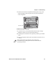
Chapter 6 — Troubleshooting 2 Check the area between the printhead and the printer cavity. If the ribbon cartridge touches the pivot frame, the printer mechanism needs realignment. Pivot frame Printhead at far left in the printer 3 Loosen the four screws that hold the mechanism in place using a Phillips screwdriver (see the following illustration). 4 Push the printer mechanism to the right away from the green thumb wheel.
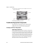
Chapter 6 — Troubleshooting 6 Hold the printer mechanism in place and tighten the screws in the sequence shown below. 1 Top right 3 Top left 2 Bottom left 4 Bottom right Four screws hold down the printer mechanism Troubleshooting System Components The printing system is composed of four basic components: printer, computer, power source, and communications. Any one of these components can prevent the printer from functioning properly.
Chapter 6 — Troubleshooting Printer Verification If the power indicator works properly and the printer still does not print, then printer errors are noted. If any indicators light when you press the Set Page button, or the printer beeps, refer to the Printer Failure Indicators table on page 102 to determine the problem. If none of the listed conditions are indicated by the beep codes and LEDs, yet the printer does not perform properly, then perform a printer self-test.
Chapter 6 — Troubleshooting If the protocol options match, then the communications cable may be defective. To determine if the cable is working, substitute a new cable. If the PC is suspect, substitute a different PC. A defective computer dock might be another possibility. Understanding Printer Errors Printer Errors are divided into classes: • Runtime errors • POST errors, • Fatal errors (consisting of flash write errors and EEPROM block errors).
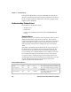
Chapter 6 — Troubleshooting Printer Failure Indicators (continued) Sets of Beeps Paper Out Head Jam Low Batt Meaning 1 set of 4 beeps Off Off 4 blinks 1 set of 13 beeps 2 sets of 2 beeps 2 sets of 3 beeps 2 sets of 4 beeps 5 sets of 2 beeps Off Off On Off 5 blinks Off 2 blinks Off On 5 blinks Off 2 blinks Off Off 5 blinks 3 sets of 2 beeps 3 blinks Off 3 blinks 3 sets of 4 beeps 4 sets of 2 beeps 12 sets of 12 beeps Off 4 blinks Off 3 blinks 4 blinks Off Off Off Off 24 V over voltage fau
Chapter 6 — Troubleshooting 3 Press the Reset button to start the POST. When the POST starts, green Power LED will come on followed by a single beep indicating that the printer is active. Note: After the test is completed, all LEDs turn off and the printhead moves to the home position. Only runtime errors or fatal errors are reported until the next time the printer is reset and POST is performed. The printer emits beeps and flashes the LEDs to indicate the cause of any POST errors.
Chapter 6 — Troubleshooting The octal digit changes every four beeps until four octal digits are output. Only four octal digits are output since blocks are 256 bytes in size and flash can be addressed with a total of 0x7ff blocks. The segment address output is the runtime address of the flash block and not the offset of the block within flash. To obtain the block offset within the flash • Subtract 0x800 from the address output to determine the block offset.
Chapter 6 — Troubleshooting Font Module Verification A CRC is performed on the font modules, which are loaded into writable flash font memory. The calculated CRC is compared to the CRC embedded in the program module. Results are printed on the self-test report. A2D Check Current reading of the A2D sources are performed, and the results are printed on the self-test report. Nonvolatile Diagnostic Memory Verification A CRC is performed on the area of the nonvolatile diagnostic memory that has a CRC over it.
Chapter 6 — Troubleshooting A self-test is equivalent to a warm start. Both are performed when you simultaneously press Form Feed and Set Page buttons on the control panel for a few seconds. Release the buttons when the printer beeps and all indicators are lit. If you press the buttons for too long, the self-test will not happen and the printer will form-feed one page. As the self-test progresses, the indicator lights change. Internal tests are performed and the two page report is printed.
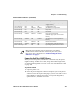
Chapter 6 — Troubleshooting • Battery Voltage, (line 13) Indicates the input voltage sampled at the beginning of the self-test. The input range must be between 7.5 and 15 V. The input voltage must be greater than 10.5 V to charge the internal battery. At 7.5 V or less, the Low Batt LED comes on and the printer enters Sleep mode. At 10.5 V or less, the Low Batt comes on but the printer still prints. • Auto Feed (line 16) Auto feed is a configurable item. Carriage Return (CR) means no auto linefeed.
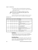
Chapter 6 — Troubleshooting Head Jam History Information (continued) Heading Description Step The acceleration step at the jam. 0 means no steps were taken, 15 means all steps were taken. 1-14 indicates the printer jammed during acceleration or deceleration. The ambient temperature at the last head jam. The temperature is listed in Celsius. Position of carriage at the time of the jam in 1/720 in = 12 * step position. Divide the number by 12 to get the step position. There are 512 steps across the page.
Chapter 6 — Troubleshooting Error Log Information (continued) Heading Description ADErr EEErr Dlink Number of A2D conversion failures Number of EEPROM write failures to diagnostic block Number of software memory errors (corruption in internal memory) Number of software memory errors Llink Sample First Page of the Self-Test Note: Lines 15-18 are factory default printer settings. Take note of these lines when reading the self-test report.
Chapter 6 — Troubleshooting Sample Second Page of the Self-Test Page 2 of the self-test contains the print pattern used to diagnose printer mechanical behavior. The pattern continuously prints the ASCII characters between 33 and 126 decimal inclusive for the entire page, or until you cancel the print by pressing a button on the printer. An example of that rotating pattern is shown below. !”#$%’()*+,–./ 0123456789:;<=>?@ABCDEFGHIJKLMNOPQRSTUVWXYZ[\]^_’abcdefghijklmnopqrstuvwxyz{|}~!”#$%’ ()*+,–.
Chapter 6 — Troubleshooting Possible Printer Problems (continued) Symptom Test or Cause Solution Does not print extended Check line 11 or 12 on the character set — missing font. self–test report to see if the NFT0000.MOD file is listed after Font Module. Printer emits 1 or 2 beeps or Printer mechanism does not blinking green light is the have adequate power for only indicator. printing. The 12 V may be under or over voltage fault.
Chapter 6 — Troubleshooting Possible Printer Problems (continued) Symptom Test or Cause Replace the paper. Straighten the white ribbon cables. Solution If “0,” realign mechanism in pivot tray. See “Aligning the Printer Mechanism” on page 98 No paper feed (paper jam or Move the printhead manually Remove ribbon cartridge, move head jam) from side to side. printhead. If smooth, ribbon is jammed. Remove ribbon cartridge, move printhead. If still resistant, mask spring is bent or damaged.
Chapter 6 — Troubleshooting Compatibility Issues Use the following information to determine some compatibility issues that come up relative to the 6822:I Compatibility Issues and Conclusions Issue Conclusion Does a 6820 ribbon work on the 6822? Do 6820 applications work on the 6822? Yes. Yes. Applications that work on the 6820 also work on the 6822. Does the 6822 work with an application Yes.
Chapter 6 — Troubleshooting Diagnostic Information Field Id 01 08 Stored as 4 3 7 digit BCD set at MFG 39 bytes 6 digit BCD set at MFG 52 digit BCD set at MFG 7 7 7 7 2 8 1 09 10 3 2 2 2 2 2 1 20 2 2 2 2 1 30 Total Length Length Description 2 2 2 Serial Number Date of Manufacture, yy/mm/dd Hardware Configuration ddd-ddd-ddd/ddd (top level P/N) ddd-ddd-ddd/ddd (control board) ddd-ddd-ddd/ddd (power supply) ddd-ddd-ddd/ddd (I/O board) CRC of preceding fields Hardware Revisions: ECNs.
Chapter 6 — Troubleshooting Diagnostic Information (continued) Field Id Length Description Stored as 2 Temperature, min/max over printer life. Set A2D value Temperature error.
Chapter 6 — Troubleshooting Diagnostic Information (continued) Field Id Length Description Stored as 4 4 bytes 4 4 4 4 4 4 4 4 4 70 2 2 2 2 2 2 2 2 2 2 2 2 2 2 2 IrDA rxFrameCrcErr – total frames received with CRC error IrDA rxTotalBytes – total bytes received OK IrDA rxFramesDiscardBuf – total frames discarded due to no buffer space IrDA rxBroadcastFrames – total broadcast frames received OK IrDA rxFramesDiscardHwErr – total received frames discarded due to hardware error IrDA txFramesOK – total f
Chapter 6 — Troubleshooting Diagnostic Information (continued) Field Id 118 Length Description Stored as 2 2 2 bytes 20 * 2 bytes Out of buffers error count Unused Total Length 6822 Series 80-Column Printer User’s Manual
Chapter 6 — Troubleshooting Communications Pin-Out Configurations This section shows common cable configurations between a mobile computer or a dock and the printer.
Chapter 6 — Troubleshooting Wall Mount Printer PC Signal Name Pin # Pin # Signal Name DTR (Data Terminal Ready)* RC (Receive Carrier) TC (Transmit Carrier) DCD (Data Carrier Detect) SG (Signal Ground) DSR (Data Set Ready)* CTS (Clear to Send) RTS (Ready to Send) RXD (Receive Data) TXD (Transmit Data) 20 17 15 8 7 6 5 4 3 2 20 17 15 8 7 6 5 4 3 2 NC (No Connection) NC NC NC GND DTR RTS CTS TXD RXD * Signals are not available on the 6100 Dock 1 14 13 25 13 25 14 1 25-Pin DSUB Male 25-Pin D
Chapter 6 — Troubleshooting Printer PC Signal Name Pin # Pin # Signal Name TXD (Transmit Data) RXD (Receive Data) RTS (Ready to Send) CTS (Clear to Send) DSR (Data Set Ready) SG (Signal Ground) 3 2 7 8 6 5 4 5 3 6 7 9 RCT TXD CTS RTS DTR (Data Terminal Ready) GND Chassis Ground shell shell 8 Chassis Ground Terminal Charge out to computer shield 1 1 5 9 6 9 15 8 9-Pin DSUB Female 9-Pin to 15-Pin Cable (P/N 226-016-XXX) 15-Pin DSUB Female 9-Pin to 15-Pin Cable (P/N 226-016-XXX) 6822 Se
Chapter 6 — Troubleshooting Printer w/6210 Terminal Holder Dock Signal Name Pin # Pin # Signal Name TXD (Transmit Data) DTR (Data Terminal Ready) RTS (Ready to Send) RXD (Receive Data) CTS (Clear to Send) DSR (Data Set Ready)* SG (Signal Ground) 2 20 4 3 5 6 7 4 2 3 5 6 7 9 RXD NC (No Connection) CTS TXD RTS DTR GND open shield shell * Signal is not available on the 6100 Dock 13 25 8 1 14 15 9 1 15-Pin DSUB Female 25-Pin DSUB Male 25-Pin to 15-Pin Cable (P/N 226-162-XXX) 25-Pin to 15
Chapter 6 — Troubleshooting Printer PC 5 Pin # Pin # 7 5 3 2 8 6 5 3 2 1 9 6 1 6 1 RJ-11 Jack 9-Pin DSUB Male Data Communications Cable (P/N 226-270-XXX) Data Communications Cable (P/N 226-270-XXX) The printer has a 25-pin connector with the following pinout designations and signal mnemonics: Printer Communications Connector 15-Pin 25–Pin D–Sub D–Sub Signal Name Type I/O Description 1 2 3 4 5 6 ––– RS-232 RS-232 RS-232 RS-232 RS-232 ––– IN IN IN OUT OUT NC (No Connection) Printer’s DS
Chapter 6 — Troubleshooting Printer Communications Connector (continued) 15-Pin 25–Pin D–Sub D–Sub Signal Name Type I/O Description 7 6 RS-232 OUT Printer’s DTR 8 9 9 7 POWER POWER OUT 11-13 V, 2 A maximum SG (Signal Ground) 124 DTR (Data Terminal Ready) HHC_CHARGE GND 6822 Series 80-Column Printer User’s Manual
A Specifications This appendix provides physical specifications for the 6822 printer models as well as specifications for the media used with the printers.
Appendix A — Specifications Specifications Print Speed 230 cps Note: Various print fonts do affect the print speed. Weight Fixed Mount Printers6.55 kg (14.41 lbs) Portable Printers w/ 4000 or 61XX terminal holder5.80 kg (12.75 lbs) w/ 62XX, 600 series, 700 series, or CK60 holder5.67 kg (12.25 lbs) Mounting plate1.93 kg (4.25 lbs) Flat paper tray2.45 kg (5.40 lbs) Compact paper tray2.05 kg (4.
Appendix A — Specifications ESD 15 kV noncontact and 8 kV contact Battery Shelf Life 1 year at 25°C (77° F) 2.3 Ah 12 V sealed lead-acid) Note: The battery goes dead within two weeks when connected to the printer and with no external charge source. Note: A printer and a computer, using the supplied serial cable, can operate up to 9 m (30 ft) apart. Printer Dimensions Listed below are the dimensions of the fixed mount and portable printers. Fixed Mount Printer The base of the fixed mount printer is 32.
Appendix A — Specifications Portable Printer The portable printer may come with a handle, an AC foot, or with a terminal holder top mount. Portable Printer Dimensions Configuration Width with handle, 61XX Holder Top Mount, and Deep Paper 41.9 cm Tray (16.5 in) with handle, 61XX Holder Top Mount, Shallow Paper Tray 42.5 cm (16.8 in) with handle, 4000 Series, 62XX, 600 Series, 700 Series, or 38.1 cm CK60 Holder Top Mount, and Deep Paper Tray (15.
Appendix A — Specifications Material Breakdown The following tables show the material broken down per ply: 14# CBF (Carbonless Back and Front) Target Under Over Basis Weight 14 lb 13.3 lb 14.7 lb Caliper 2.9 2.6 3.2 Moisture 5.0 4.0 6.0 Smoothness (RS) 165 110 230 Smoothness (CB) 270 220 320 Brightness (Wht) 88 86 90 Colors available: White, Canary, Pink, Goldenrod, Blue, Green 15# CF (Carbonless Front) Target Under Over Basis Weight 15 lb 14.43 lb 15.8 lb Caliper 3.0 2.5 3.2 Moisture 5.0 4.0 6.
Appendix A — Specifications 20# OCR Laser Bond Basis Weight Caliper Moisture Smoothness Brightness (Wht) Opacity (Wht) Target Under Over 20 lb 4.0 3.8 140 94 85 15.2 lb 3.8 4.7 100 82 84 16.8 lb 4.2 5.0 170 N/A N/A Caliper Breakdown The following table shows the caliper of forms broken down by ply: Caliper Breakdown 1-Ply (20 lb) 2-Ply (15 lb and 16 lb) 3-Ply (14 lb, 15 lb, and 16 lb) 130 Target Maximum 4.0 6.3 9.2 4.2 7.0 10.
Appendix A — Specifications Understanding the Fanfold Paper Page Layout The following illustration shows the printable area of the lower section of a page of fanfold paper and the upper section of the next page. The Assured Print Area is the best area to use for printing. Page width Assured Print Area 8 inches Max. (area 2) 0.75 inch (or more) Assured Print Area 55 lines max (at 1/16” line spacing) (area 2) 0.75 inch (or more) Paper End Detection Position Abcdef... 1 inch ...Xyz (area 3) 1.
Appendix A — Specifications • The top and bottom margins are represented by Area 1, as shown in the previous illustration. The top margin is defined as the distance between the top edge of the paper and the first row of printed characters. The bottom margin is defined as the distance between the last row of printed characters and the bottom edge of the paper.