Installation and Quick Start Guide IM5 Reader Module
Packing List Check to ensure that you receive these items: S IntermecR IM5 Reader Module S Compliance Statement S Warranty Card Host Communication Host communication comes through the 9-pin female D-sub connector. RS-232 standards are supported as ordered from the factory or service center. S The maximum data rate is 115.2K baud, with 8 data bits, no parity bit, and 1 stop bit. S The maximum RS-232 distance from the reader to the host, modem, or other physical controller interface is 50 feet (15.2 meters).
User I/O A general purpose I/O (Input/Output) connector provides signal lines in and out of the reader allowing monitoring and/or control of external devices or functions. The connector for this is a 13-pin female circular DIN. The mating male connector you need for mating with this is an Intermec p/n: 351-184-001.
Installing the IM5 Reader Module The IM5 Reader Module requires 8-10 volts DC at 2 amps. The IF4 Serial Reader is powered through a 2-pin bulkhead barrel connector (Switchcraft p/n: 712A). The Reader Module supplies 9-volt 2.4 amps to this connector. Mating plugs for this connector are Switchcraft part numbers 760, 760K or 761K. A cable within the PSR connects the bulkhead barrel connector, via an endplate switch, to the 2-pin Molex connector on the IM5 Reader Module.
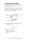
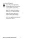
Connecting and Getting Started FCC and Industry Canada regulations limit exposure to radiofrequency (RF) radiation. To comply with these regulations, operators of this device must maintain a distance of at least 23 cm. (9.1 inches) from the cover on the antenna assembly (The cover on the antenna is the dome shaped surface). While the device is on, the operator’s body and parts of the body such as eyes, hands, or head, must be 23 cm. (9.1 inches) or farther from the cover of the antenna assembly.
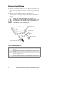
Antenna Installation 1 Connect the antenna cable to a port. The four antenna connectors have lock washers and nuts to allow for panel mounting. 2 Connect a reverse SMA terminator (Intermec p/n 345-004-001) to any port that does not have an antenna attached. Each port must have either an antenna or a terminator connected. Do not apply power to the Reader unless an antenna cable or terminator is installed on each antenna port.
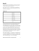
Troubleshooting Troubleshooting Doesn’t Recognize Tag 1. Ensure antenna is properly connected. 2. Ensure reader is connected to your computer. 3. Ensure computer is plugged into AC outlet and computer is On. 4. Ensure tag is within range of antenna. 5. Call Intermec Technical Support 1-800-755-5505 (option 2). Product Specifications Dependent upon operating conditions and demands expected. If used in a normal office environment with good read conditions, you could expect to read up to 60 tags per second.
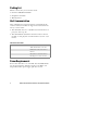
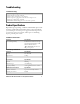
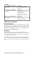
General Specifications (continued) Physical Specifications Spec Detail Size 8.25 in. x 5.30 in. x 2.9 in. Weight 38.4 oz. (1.1 kg) Frequency reference Source Spec Detail Frequency of operation 902-928 MHz Usable channels 51 Transmitter Spec Detail Output power 1.
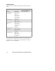
Reliability Safety and Regulatory Approvals Spec Detail Reader module UL 60950-1-UL Recognized Component. Electromagnetic Compatibility Spec Detail Reader Module EN55022 (CISPR 22) Class B digital emissions EN55024 Immunity EN61000-3-2, -3 AC Power Harmonic Emissions and Flicker Radio Frequency Device Approval Spec Detail Reader Module FCC Part 15.
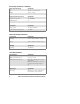
Telephone Support These services are available from Intermec Technologies Corporation. In the U.S.A. and Canada call 1-800-755-5505 and choose this option Service Description Factory Repair and On-site Repair Request a return authorization number for authorized service center repair, or request an on-site repair technician. 1 Technical Support Get technical support on your Intermec product. 2 Service Contract Status Inquire about an existing contract, renew a contract, or ask invoicing questions.
IM5 Reader Module Installat ion and Quick Start Guide 11
Corporate Headquarters 6001 36th Avenue West Everett, Washington 98203 U.S.A. tel 425.348.2600 fax 425.355.9551 www.intermec.com e 2004 by Intermec Technologies Corporation. All rights reserved.