
Quick Start Guide

3
IM5 Reader Module Installat ion and Quick Start Guide
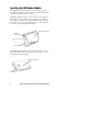
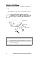
User I/O
A general purpose I/O (Input/Output) connector provides sig-
nal lines in and out of the reader allowing monitoring and/or
control of external devices or functions.
Theconnectorforthisisa13-pinfemalecircularDIN.The
mating male connector you need for mating with this is an In-
termec p/n: 351-184-001.
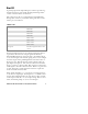
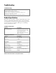
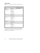
I/O Pin-outs
Pin Number Definition
1 GPIO IN0
2 GPIO IN1
3 GPIO IN2
4 GPIO IN3
5 GPIO OUT0
6 GPIO OUT1
7 GPIO OUT2
8 GPIO OUT3
9 through 13 Ground through individual 10 ohm
resistors
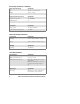
Outputs and inputs have 12 volt transient suppression devices
to ground at the connector. Output signals are driven by
2N3904 NPN transistors (low level) with a 100 kohm pull-up
to +5 volts through a silicon diode, giving about a 4.3 volt high
level. An output can be pulled high from an external source as
high as 12 volts. This will however tend to pull the other out-
puts higher (through two 100k resistors). The low level will be
about0.1voltuptoabout30mA.Theoutputlowvoltagewill
climb higher as the sink current increases. There is no protection
on this. You need to ensure that their load won’t require the
reader to sink more than 50 mA.
Input signals should be 0 to +1.5 volt for a low input and +3.5
to +5 volts for a high input. Each input has a 1.1 kohm resistor
in series with clamping diodes, but only about 1 µAisusedun-
til the input exceeds the 0 to +5 volt input range. There is also a
weak (100 kohm) pull-up to +5 volt on each input.