
Datasheet
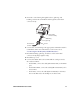
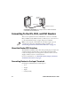
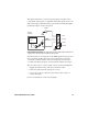
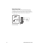
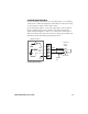
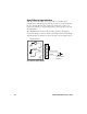
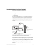
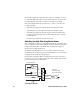
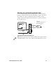
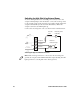
Table Of Contents
- About the GPIO Terminal Block
- Installing the Terminal Block
- Connecting To the IF5, IF30, and IF61 Readers
- Connecting To the IV7 Vehicle-Mount Reader
- Where to Go From Here
- Specifications and Pinouts
12 GPIO Terminal Block User’s Guide
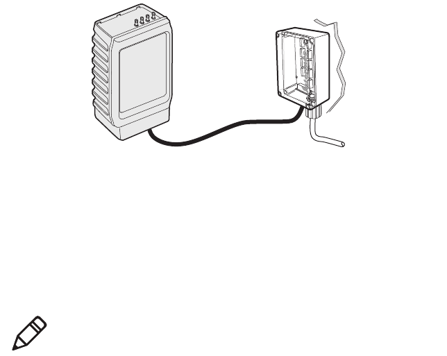
Connecting to the Reader: This example shows an IF61 Fixed Reader
connected to the terminal block.
Connecting To the IF5, IF30, and IF61 Readers
This section explains how the terminal block connects to the IF5,
IF30, and IF61 reader GPIO interfaces, and how you connect devices
to the terminal block input, output, and power terminals.
About the Reader GPIO Interface
The IF5, IF30, and IF61 readers have four general purpose input and
output interfaces. Each interface is electrically isolated from the
reader and designed for low voltage DC loads. The readers can also
supply 12 VDC at 0.5 A to external devices.
For more information, see “About the Input, Output, and Power
Terminal Connections” on page 8.
Connecting Devices to the Input Terminals
Each input terminal has four terminal posts:
• 12 V
• +Input
• -Input
• Gnd (Ground)
Terminal
block
GPIO cable
IF61
To industrial controls
Note: Connecting the terminal block to the IV7 requires special
considerations. For more information and a schematic, see
“Connecting To the IV7 Vehicle-Mount Reader” on page 23.