
User guide
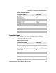


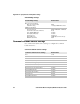
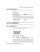
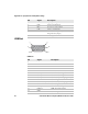

Table Of Contents
- Send Feedback
- Before You Begin
- Chapter 1 - About the Vehicle Mount Computer
- Chapter 2 - Understand the User Interface and Intermec Applications
- Chapter 3 - Manage the Computer
- Chapter 4 - Configure the Computer
- Chapter 5 - Troubleshoot and Maintain the Computer
- Chapter 6 - Upgrade the CV61 Vehicle Mount Computer
- Appendix A - Specifications and Default Settings
- Appendix B - ScanNGo Wi-Fi Configuration Bar Codes
Appendix A — Specifications and Default Settings
98 CV61 Vehicle Mount Computer (Windows XP) User Guide
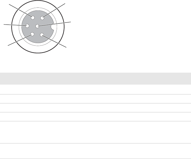
Power Supply Connector
Pin Signal Description
1
GND
Chassis ground
2 DC+ 12 V, 4 A from external DC supply
3DC-/V In-Input -
4HTR-Input -
5 HTR+ 12 V, 4 A from external DC supply (only
required if the CV61 has optional heated
defroster)
6 V In+ 10 to 60 V (Input to internal DC/DC power
supply)
1
2
3
4
5
6