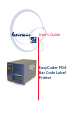
User’s Guide EasyCoder PD4 Bar Code Label Printer
Intermec Technologies Corporation Corporate Headquarters 6001 36th Ave. W. Everett, WA 98203 U.S.A. www.intermec.com The information contained herein is proprietary and is provided solely for the purpose of allowing customers to operate and service Intermecmanufactured equipment and is not to be released, reproduced, or used for any other purpose without written permission of Intermec.
FCC Notice (United States of America) WARNING This equipment generates, uses, and can radiate radio frequency energy and if not installed and used in accordance with the instructions manual, may cause interference to radio communications. It has been tested and found to comply with the limits for a Class A computing device pursuant to Subpart J of Part 15 of FCC Rules, which are designed to provide reasonable protection against such interference when operated in a commercial environment.
iv Intermec EasyCoder PD4—User’s Guide
Contents Contents Before You Begin......................................................................... viii Safety Summary ............................................................ viii Safety Icons .................................................................... ix Global Services and Support .......................................................... x Warranty Information...................................................... x Web Support ......................................................
Contents 4 Loading Media 5 Printing 6 Options 7 Troubleshooting 8 Maintaining the Printer 9 Adjustments vi Tear-Off (Straight-through) .........................................................20 Peel-Off (Self-strip) ..................................................................... 25 Thermal Transfer Printing ............................................................29 Ribbon Load ................................................................................30 Controlling the Printing.
Contents A B Technical Data Table of Technical Data ................................................................70 Media Specifications Media Roll Size ............................................................................74 Core ..............................................................................74 Internal Roll .................................................................. 74 Media ..........................................................................................
Before You Begin Before You Begin This section provides you with safety information, technical support information, and sources for additional product information. Safety Summary Your safety is extremely important. Read and follow all warnings and cautions in this document before handling and operating Intermec equipment. You can be seriously injured, and equipment and data can be damaged if you do not follow the safety warnings and cautions.
Before You Begin Safety Icons This section explains how to identify and understand dangers, warnings, cautions, and notes that are in this document. You may also see icons that tell you when to follow ESD procedures. A warning alerts you of an operating procedure, practice, condition, or statement that must be strictly observed to avoid death or serious injury to the persons working on the equipment.
Before You Begin Global Services and Support Warranty Information To understand the warranty for your Intermec product, visit the Intermec web site at http://www.intermec.com and click Service & Support. The Intermec Global Sales & Service page appears. From the Service & Support menu, move your pointer over Support, and then click Warranty. Web Support Visit the Intermec web site at http://www.intermec.com to download our current documents in PDF format.
1 Introduction This chapter introduces the EasyCoder PD4 printer.
Chapter 1—Introduction Description of EasyCoder PD4 The EasyCoder PD4 is a basic-performance thermal transfer/direct thermal label printer suitable for medium-duty industrial applications. With robust metal outer casing and inner mechanics, the EasyCoder PD4 provides durability, even in industrial environments.
Chapter 1—Introduction Safety Warnings • Read this manual carefully before connecting the printer. • Moving parts are exposed when the side door is open, so ensure that the door is closed before you operate the printer. • Do not open the front/left-hand cover. Dangerous voltage! • Do not remove the bottom plate. Dangerous voltage! • Do not put your fingers inside the print mechanism when the power is on. • Place the printer on an even surface which can support its weight of approximately 13 kg (28.
Chapter 1—Introduction 4 Intermec EasyCoder PD4—User’s Guide
2 Installation This chapter explains how to unpack and install the EasyCoder PD4 printer and also describes the printer’s various parts in detail.
Chapter 2—Installation Unpacking the Printer Before you install the printer, examine the package for possible damage or missing parts: • Open the box and lift the printer out. • Check that the printer has not been visibly damaged during transportation. Keep the packing materials in case you need to move or reship the printer. • Check the label on the printer’s rear plate, which gives the voltage, the part number, and the serial number. • Check that any options you ordered are included.
Chapter 2—Installation Front View At the front of the printer are the display window, the control lamps, and the control keys. These features allow the operator to control and set up the printer manually as described later in this chapter. The printed labels, tickets, or tags are presented at the front of the print mechanism. The front cover can be removed for loading of labels at peeloff (self-strip) operation and for installation of a cutter (options).
Chapter 2—Installation Rear View The rear plate contains the On/Off switch, the AC power cord socket, and various interface connectors and slots.
Chapter 2—Installation Media Compartment The media compartment is covered by a side door that completely encloses the print mechanism and media compartment. It can be opened 180° to provide full access to the media compartment. The inspection window allows checking how much ribbon and media remains without having to open the door. The media can be supplied from a supply post, or from an external supply of fan folds behind the printer.
Chapter 2—Installation Print Mechanism The print mechanism features either an 8 dot/mm (203.2 dots/inch) or 11.81 dots/mm (300 dots/inch) quick-mount thermal printhead. In front of the print mechanism is a fold-out label taken sensor, which can hold the printing of next label until the previous one has been removed.
Chapter 2—Installation Connections Power 1 Place the printer on a level surface, near an AC outlet. You should be able to easily access the printer to load media and to remove the printout. 2 Both the printer and the host computer must be switched off while they are being connected. 3 Connect the power cord between the receptacle on the rear plate and to the electrical outlet (100 to 240 VAC).
Chapter 2—Installation Controls and Indicators The EasyCoder PD4 has several ways of communicating directly with its operator: • Three control lamps, • a graphic display window with background illumination, • three control keys, • and a beeper. Control Lamps The LED (Light Emitting Diode) control lamps are labelled “Power”, “Ready”, and “Error.” • Power (solid green) indicates that the power is on. • Ready (solid green) indicates that the printer is ready for use.
Chapter 2—Installation Key Functions Mode Feed key Pause key Cancel key Startup Print test label or Enter Dump Mode (press >3 sec.
Chapter 2—Installation 14 Intermec EasyCoder PD4—User’s Guide
3 Starting Up This chapter explains how to start up the printer after installation or after having been switched off.
Chapter 3—Starting Up Switching On the Printer Before switching on the printer, make the necessary connections, and check that the printhead is engaged (in the lower position). Switch on the power using the On/Off switch on the rear plate. The green “Power” control lamp on the front panel lights up when the power is on. Wait for a few moments, while the printer starts up. Provided the printer is fitted with a display, the following message is shown: The startup takes just a few seconds.
Chapter 3—Starting Up Direct Mode The Direct Mode is the normal idle mode, where all commands from external ports are interpreted and normal control key actions are performed. During reception of data, this message is shown in the display: In the Direct Mode, you can use the keys for the following purposes: • Feed out one blank label or portion of continuous stock by pressing the Feed key. • Pause the Direct Mode by pressing the Pause key.
Chapter 3—Starting Up Printing a Test Label An easy way to check that the printer is working and find out how it is presently set up is to print a test label. The test label can also be used to check the printout quality. • Switch off the power to the printer. • For best result, load the printer with full width labels or tags and transfer ribbon as described in Chapter 4. • Hold down the Feed key and turn on the power again. • Release the Feed key within 3 seconds.
4 Loading Media This chapter explains how to load the printer with media, that is labels, tickets, tag, or strips, as well as transfer ribbon, for the following modes of operation: • Tear-Off (straight-through) • Peel-Off (self-strip, requires an optional stripper and internal rewinder) • Thermal transfer printing Intermec EasyCoder PD4—User’s Guide 19
Chapter 4— Loading Media Tear-Off (Straight-through) The EasyCoder PD4 can print on labels, tickets, tags, and continuous stock in various forms. This section describes the case when the media is torn off manually against the printer’s tear bar. This method is also known as “straight-through printing.
Chapter 4—Loading Media Tear-Off, cont. 1 2 Open the side door. 3 Pull out the printhead lever and flip it counterclockwise a quarter of a turn. 4 Flip the label feed guide upward. Intermec EasyCoder PD4—User’s Guide Place the media roll onto the media supply roll post and align the media to the printer's center section.
Chapter 4—Loading Media Tear-Off, cont. 5 Align the edge guide with the media roll. Avoid placing the guide so it breaks the rotation of the roll. 22 6 Route the media between the two label feed rods and under the moveable sensor to the tear bar. 7 8 This diagram shows the media path when using and internal supply. This diagram shows the media path when using an external supply of, for example, fan-folded tickets.
Chapter 4—Loading Media Tear-Off, cont. 9 Align the media with the center section and adjust the label feed guide. Flip the guide back so it snaps to the rear label feed rod and close the printhead. 11 When in use, the label taken sensor should be in a horizontal position. Intermec EasyCoder PD4—User’s Guide 10 Optionally, press the lower part of the label taken sensor to flip it open. 12 Close the side door.
Chapter 4—Loading Media Tear-Off, cont. 13 Press the Feed key to advance the media and adjust the media feed.
Chapter 4—Loading Media Peel-Off (Self-strip) The EasyCoder PD4 can print on labels, tickets, tags, and continuous stock in various forms. This section describes the case when self-adhesive labels are separated from the liner immediately after printing. The liner is then wound up on an optional integral liner takeup hub (see Chapter 6 “Options”). This is also known as “Self-strip” operation.
Chapter 4—Loading Media Peel-Off, cont. 1 2 Screw Unscrew the front cover screw and remove the front cover. 3 Peel off the labels from the first 40 cm (16 in) of the liner and route the liner around the tear bar, then back under the print mechanism and label feed rods to the takeup hub. 26 Install the media as described for TearOff operation #1 to #6 earlier in this chapter. 4 Wrap the liner counterclockwise around the takeup hub and secure it with the U-shaped clip.
Chapter 4—Loading Media Peel-Off, cont. 5 Align the media with the center section and adjust the label feed guide. Flip the guide back so it snaps to the rear label feed rod and close the printhead. 7 Optionally, press the lower part of the label taken sensor to flip it open. Intermec EasyCoder PD4—User’s Guide 6 Put back the front cover and secure it with the screw. 8 When in use, the label taken sensor should be in a horizontal position.
Chapter 4—Loading Media Peel-Off, cont. 9 10 Close the side door. 28 Press the Feed key to advance the media and adjust the media feed.
Chapter 4—Loading Media Thermal Transfer Printing The EasyCoder PD4 can print on labels, tickets, tags, and continuous stock using either direct thermal printing on special heat-sensitive media or thermal transfer printing using a special ink-coated ribbon. Thermal transfer printing makes it possible to use a wide range of receiving face materials and gives a durable printout less vulnerable to fat, chemicals, heat, sunlight etc. than direct thermal printing.
Chapter 4—Loading Media Ribbon Load 1 2 Open the side door. 3 4a B A Load a fresh ribbon roll onto the ribbon supply shaft (A) and an empty ribbon core onto the ribbon rewind shaft (B). 30 Pull out the printhead lever and flip it counterclockwise a quarter of a turn. Ink facing outward on ribbon roll: Route the ribbon as illustrated and stick it to the take-up core.
Chapter 4—Loading Media Ribbon Load, cont. 4b 5 Ink outside the roll Ink inside the roll Ink facing inward on ribbon roll: Route the ribbon as illustrated and stick it to the take-up core. Check that the ink position lever above the ribbon supply hub is in correct position. 6 Flip the printhead lever back to its original position and close the side door.
Chapter 4— Loading Media 32 Intermec EasyCoder PD4—User’s Guide
5 Printing This chapter describes how the operator can control the printing. Additionally, it describes the various parameters that are accessible in the Setup Mode to configure the printer for the user’s specific requirements. All these parameters and several others can also be set using ESim commands.
Chapter 5—Printing Controlling the Printing The printing is initiated from the host computer, but the operator can control batch printing, that is, the printing of multiple labels. Printing can only be performed when the printer is in the Direct Mode (see Chapter 3). During printing, the optional display shows the quantity of printed labels or similar: The operator can temporarily pause the printing by pressing the Pause key.
Chapter 5—Printing Setup Methods The EasyCoder PD4 can be set up using two methods: • Using ESim Commands This method support all setup parameters and uses various ESim commands transmitted from the host computer to the printer. Please refer to ESim v5.xx for EasyCoder PD4, Programmer’s Reference Manual. • Using the display window and keys on the printer’s front panel. This method only supports some setup parameters, namely those that are important for the operator.
Chapter 5—Printing Setup Options Media Type Note Direct Thermal Default Thermal Transfer Density (see note on the next page) 1 (lightest image) ....
Chapter 5—Printing Note: Do not use a higher density setting than required for your media and application. Lower density setting saves your printhead and extends its life.
Chapter 5—Printing 38 Intermec EasyCoder PD4—User’s Guide
6 Options This chapter describes the options available for the EasyCoder PD4 printer. The options can be factory installed, field-installed by an authorized service technician, or installed by a trained operator.
Chapter 6—Options Stripper and Internal Rewinder Installation Instructions 1 Remove the screw that holds the front cover. Remove the front cover. Front cover Screw 2 Open the side door and remove the rewinder option cover plate, which is held by two Phillips screws.
Chapter 6—Options 3 Remove the U-shaped clip and attach the rewinder unit to the center section using the four screws included in the kit. 4 Plug in the cable from the rewinder switch into the front one of the two connectors in the center section. Switch Rewinder cable 5 Install the media as described in Chapter 4 “Media Load”, section “Peel-off (Self-strip).
Chapter 6—Options Cutter Installation Instructions 1 Remove the screw that holds the front cover. Remove the front cover. Front cover Screw 2 Open the side door and remove the tear bar, which is held by two Phillips screws.
Chapter 6—Options 3 Attach the cutter mechanism to the printer using the two Phillips screws and washers included in the kit. 4 Plug in the cable from the cutter into the rear one of the two connectors in the center section and fasten the cable to the bottom plate using the two cable clips included in the kit.
Chapter 6—Options 5 Attach the cutter cover onto the cutter mechanism by first connecting the hooks on the back side of the cover over the cutter mechanism and then locking the cover with the screw at the bottom. 6 If needed, fit the tray to the front of the cutter. 7 Install the media as described in Chapter 4 “Media Load”, section “Tear-off (Straight-through)”. Recommended label/paper length is at least 30 mm (1.18 in).
7 Troubleshooting This chapter lists various possible cases of inferior printout quality, describes possible causes, and suggests remedies.
Chapter 7—Troubleshooting Error Handling When an error occurs, the Error LED goes solid or flashing red and the beeper emits two beeps. Provided the printer is fitted with a display, two error message are displayed alternatingly, for example: When all errors have been cleared, the Error LED goes off, the beeper emits a single beep, and the printer returns to the same mode as when the error occurred, which is indicated in the display window.
Chapter 7—Troubleshooting Error Suggested action Check the power cable The Power control lamp does not shine and the LCD display (if any) shows no message after the power has been switched on Error LED light turns solid red after printing stops Check for bad software setting or ESim command errors Check if printer is out of media or ribbon Check if media is jammed/tangled up Check if mechanism is not locked and closed Check if label gap sensor is blocked by media Check cutter (if any) Printing started,
Chapter 7—Troubleshooting Printout not in desired position Check for bad settings in the application or ESim command errors Check if label gap sensor is disturbed by media, dust, or erroneously loaded transfer ribbon Check lateral position of label gap sensor Calibrate label gap sensor in Autoadjust Mode Check the edge guide and media guides Check the media (too little liner transparency, weak black marks, or interfering preprint at the back of the media?) Check if platen roller needs cleaning or replaceme
Chapter 7—Troubleshooting Clearing Media Jam in Cutter To clear a media jam inside the cutter mechanism, follow the instructions below: 1 At media jams and cutter malfunctions, switch off the power to the printer. Never insert fingers or tools into the printer while the power is still on. 2 Insert a 3 mm hexagon screwdriver in the hole on the side of the cutter (A) and turn the cutter blade clockwise.
Chapter 7—Troubleshooting Entering the Dump Mode In the Dump Mode, the printer prints all received ASCII characters including control characters (ASCII 00-31 decimal). There is automatic line-wrapping and if a label becomes completely filled, the dump continues on a new label. This facility is useful for debugging. Enter the Dump Mode like this: 1 Switch off the power to the printer. 2 Press and hold the Feed key while you switch on the power again.
8 Maintaining the Printer This chapter describes how the operator can maintain the printer. Regular maintenance is important for the printout quality and for the life of the printhead. The chapter covers the following topics: • Printhead cleaning • External cleaning • Printhead replacement. • Media jams.
Chapter 8—Maintaining the Printer Printhead Cleaning Cleaning the printhead on a regular basis is important for the life of the printhead and for the printout quality. You should clean the printhead using cleaning cards or a cotton swab moistened with isopropyl alcohol, preferably each time you load a new supply of transfer ribbon. Isopropyl alcohol [(CH3)2CHOH; CAS 67-63-0] is a highly flammable, moderately toxic, and mildly irritating substance. 1 Open the side door. 2 Remove the media and ribbon.
Chapter 8—Maintaining the Printer Clean the printhead dot line.
Chapter 8—Maintaining the Printer External Cleaning Always unplug the power cord before cleaning the printer. If using the printer in an industrial environment, where the premises may be cleaned using a water hose or steam, move the printer to another room or cover it carefully with a plastic sheet and make absolutely sure that the power cord is unplugged. Clean the external surfaces using a soft cloth, possibly slightly moisten with water or a mild detergent.
Chapter 8—Maintaining the Printer Printhead Replacement The printhead is subject to wear both from the direct thermal media (or ribbon) and from the rapid heating and cooling process during printing. Thus, the printhead will require periodic replacement. Time between printhead replacements depends on the print images, the type of direct thermal media (or ribbon) in use, the amount of energy to the printhead, the print speed, the ambient temperature, and several other factors.
Chapter 8—Maintaining the Printer Media Jams Should a media jam occur in the print mechanism, proceed this way to clear it: • Always switch off the power before starting to clear the jammed media. • Raise the printhead and pull out the media. • If the media has been wound up or has stuck on the platen roller, carefully remove it by hand without using any sharp tools that can damage the delicate platen roller or printhead. Avoid rotating the platen roller.
9 Adjustments This chapter describes how the operator can adjust the printer.
Chapter 9—Adjustments Printhead Balance Adjustment The printer is factory-adjusted for full-size media width. When using media less than full width, it is recommended that you adjust the position of the printhead balance boxes so the printhead gets an even pressure across the media. A poorly adjusted printhead pressure may be detected by a weaker printout on either side of the media path. To adjust the pressure, proceed as follows: 1 Open the top cover. 2 Remove the ribbon.
Chapter 9—Adjustments Printhead Pressure Adjustment The pressure of the thermal printhead against the platen roller is factoryadjusted. However, if the printing is weaker on one side of the media or if the thermal transfer ribbon starts to crease (indicated by unprinted white streaks along the media feed direction), it may be necessary to readjust the printhead pressure. Note: Before readjusting the pressure, try to fix the problem by moving the outer balance box as described earlier in this chapter.
Chapter 9—Adjustments Printhead Dot Line Position Adjustment When using thick or stiff media, the printhead needs to be moved forward so the dot line becomes exactly aligned with the top of the platen roller. Obviously, the platen roller and printhead must also be completely in parallel. To perform this adjustment, follow the steps below: 1 Open the top cover. 2 Remove the ribbon.
Chapter 9—Adjustments 5 Turn both screws at the front of the printhead carefully clockwise a quarter of a turn at a time (a full turn corresponds to 0.5 mm which is a lot). Make sure to make identical adjustments on both the screws! If you get lost, tighten both screws by turning them counterclockwise as far as they go and start all over again. 6 Engage the printhead and Lock the printhead by tightening the two screws at the top of the printhead bracket, that is, the reverse action of step #3.
Chapter 9—Adjustments Label Gap Sensor Position Adjustment The label gap/black mark sensor is a photoelectric sensor that controls the printer’s media feed by detecting gaps between labels, or slots or black marks in continuous stock, depending on the printer’s setup in regard of media type (see Chapter 5, “Printing”). An obvious prerequisite is that the sensor must be aligned with the gaps, slots, or black marks. If usingirregularly shaped labels, align the sensor with the front tips of the labels.
Chapter 9—Adjustments Label Gap Sensor Calibration The label gap sensor will need to be calibrated and the media feed adjusted at the following occasions: • After media load when the printer is used for the first time. • After loading media that differs from the previously loaded in regard of type (gaps, black marks, or continuous), size and location of gaps or black marks, or transparency of the liner.
Chapter 9—Adjustments Ribbon Tension Adjustment If ribbon wrinkling occurs during printing, push the knob at the end of the ribbon supply hub inwards (1) and rotate it clockwise to increase the breaking force (2). If the printer have problems pulling the labels (especially when using a ribbon less than 50 mm/2 in wide), push the knob at the end of the ribbon supply hub inwards (1) and rotate it counterclockwise to decrease the breaking force (2).
Chapter 9—Adjustments Ribbon Shield Adjustment Ribbon wrinkling can also be avoided using the ribboon shield mechanism. The ribbon shield mechanism is located on the thermal printhead, and has two adjustable screws A and B shown below. A B If the label printout occurs as in Test label A, turn screw A clockwise. If the printout occurs as in Test label B, turn screw B clockwise. Turn the screw half a circle and perform a new test printing. Continue until you achieve a smooth print quality.
Chapter 9—Adjustments Switching Edge Guide As standard, the EasyCoder PD4 is fitted with a low edge guide on the media supply roll post. The low edge guide makes it simple to fit a media supply roll on the post, but it only guides the core of the roll. Therefore, the EasyCoder PD4 is delivered with an enclosed high edge guide which the user can fit quite easily when the application so requires, for example when the printer cannot be placed on a horizontal surface or when the media roll tends to unwind itself.
Chapter 9—Adjustments Edge guide Hook Washer Coil spring Post Adjust for width of media roll Fold down for media load Be careful to flip the high edge guide straight up before closing the side door, or the guide could be damaged.
Chapter 9—Adjustments 68 Intermec EasyCoder PD4—User’s Guide
A Technical Data This appendix lists the technical data for the printer. Please note that Intermec reserves the right to change without prior notice and that this information does not represent a commitment on the part of Intermec.
Appendix A—Technical Data Table of Technical Data Printing Print Technique Direct Thermal/Thermal Transfer Printhead Resolutions 8 dots/mm (203.2 dpi) or 11.81 dots/mm (300 dpi)1 Print Speed (variable) 50.8 to 152.4 mm/sec. (2 to 6 in/sec.) 50.8 to 101.6 mm/sec. (2 to 4 in/sec.) 8 dots/mm 11.81 dots/mm Print Width 25 to 104 mm (1 to 4.09 in) 25 to 106 mm (1 to 4.17 in) 8 dots/mm 11.81 dots/mm Print Length (max) 1,270 mm (50 in) 558.8 mm (22 in) 8 dots/mm 11.
Appendix A—Technical Data Asian Fonts Built-in bar code symbologies (standard) Asian fonts can be downloaded: GB 2312-80 Chinese Big5 level 1 & 2 KS X 11001:1992 JIS X0208:12977 Chinese Chinese Korean Japanese 34 Physical Measures Dimensions (W x L x H) 276 × 454.6 × 283.0 mm (10.85 × 17.9 × 11.2 in) Weight (excluding media) ≈ 13 kg (28.
Appendix A—Technical Data Data Interfaces Serial 1 x RS-232 + 1 x USB Parallel Yes Accessories and Options Integral Self-strip Unit with Liner Takeup Option1 Cutter Option1 2MB Flash Memory Expansion Module Option1 Keyboard/Display Unit Option EasyLAN 10 External Ethernet Adapter Option For peel-off operation /. Versions with graphic display front panel only.
B Media Specifications This appendix specifies the physical measures for various types of media.
Appendix B—Media Specifications Media Roll Size Core Diameters: Width: 38 to 76.2 mm (1.5 to 3 inches) Must not protrude outside the media. The media must be wound up on the core in such a way that the printer can pull the end free. Internal Roll Max. diameter: Max. width: Min. width: 212 mm 118 mm 25 mm (8.35 inches) (4.65 inches) (1.00 inches) Thickness: 6 to 250 µm (2.3 to 9.8 mils) Thicker media may be used, but print quality will be reduced.
Appendix B—Media Specifications Media Non-Adhesive Strip ⇐ a ⇒ Media Width Maximum: Minimum: 118.0 mm (4.65 inches) 25.0 mm (1.
Appendix B—Media Specifications Self-Adhesive Strip ⇐ a ⇒ Media Width (including liner) Maximum: Minimum: 118.0 mm (4.65 inches) 25.0 mm (1.00 inches) ⇐ b ⇒ Liner The liner must not extend more than a total of 1.6 mm (0.06 inches) outside the face material and should protrude equally on both sides. ⇐ c ⇒ Media Width (excluding liner) Maximum: Minimum: 116.4 mm (4.58 inches) 23.8 mm (0.
Appendix B—Media Specifications Self-Adhesive Labels ⇐ a ⇒ Media Width (including liner) Maximum: Minimum: 118.0 mm (4.65 inches) 25.0 mm (1.00 inches) ⇐ b ⇒ Liner The backing paper must not extend more than a total of 1.6 mm (0.06 inches) outside the labels and should protrude equally on both side. ⇐ c ⇒ Label Width (excluding liner) Maximum: Minimum: 116.4 mm (4.58 inches) 23.8 mm (0.94 inches) ⇐ d ⇒ Label Length Maximum: 8 dots/mm (203.2 dpi) 11.81 dots/mm (300 dpi) Minimum: 8 dots/mm (203.
Appendix B—Media Specifications a c d e SELF-ADHESIVE LABELS b b FEED DIRECTION 78 Intermec EasyCoder PD4—User’s Guide
Appendix B—Media Specifications Tickets with Gaps ⇐ a ⇒ Media Width Maximum: Minimum: 118.0 mm (4.65 inches) 25.0 mm (1.00 inches) ⇐ b ⇒ Copy Length Maximum: 8 dots/mm (203.2 dpi) 11.81 dots/mm (300 dpi) 1270 mm (50 inches) 558.8 mm (22 inches) Minimum: 8 dots/mm (203.2 dpi) 11.81 dots/mm (300 dpi) 5 mm (0.2) inches) 5 mm (0.2) inches) ⇐ c ⇒ Detection Position Variable: 0 to 57 mm (0 to 2.
Appendix B—Media Specifications a c b e d TICKETS & TAGS FEED DIRECTION 80 Intermec EasyCoder PD4—User’s Guide
Appendix B—Media Specifications Tickets with Black Mark ⇐ a ⇒ Media Width Maximum: Minimum: 118.0 mm (4.65 inches) 25.0 mm (1.00 inches) ⇐ b ⇒ Copy Length Maximum: 8 dots/mm (203.2 dpi) 11.81 dots/mm (300 dpi) 1270 mm (50 inches) 558.8 mm (22 inches) Minimum: 8 dots/mm (203.2 dpi) 11.81 dots/mm (300 dpi) 10 mm (0.39) inches) 10 mm (0.39) inches) ⇐ c ⇒ Detection Position Variable: 0 to 57 mm (0 to 2.24 inches) ⇐ d ⇒ Black Mark Width The detectable width of the black mark should be at least 5.
Appendix B—Media Specifications a b c e d f TICKETS WITH MARKS FEED DIRECTION 82 Intermec EasyCoder PD4—User’s Guide
C Interfaces This appendix describes the interface connectors found on the printer’s rear plate.
Appendix C—Interface RS-232 Interface Protocol Default setup: Baud rate: Char. Length Parity: Stop bits: Handshaking: 9600 8 bits None 1 XON/XOFF and RTS/CTS To change the RS-232 interface settings, see Chapter 5, “Printing.
Appendix C—Interfaces USB Interface This printer supports USB v1.1 (also called USB 2.0 full speed). To use the USB interface for printing from a PC, you need a special Intermec USB printer driver installed in your PC. The printer is a so called “self-powered device.” We recommend that you only connect one printer to each USB port on the host, either directly or via a hub. Other devices, like a keyboard and a mouse, can be connected to the same hub.
Appendix C—Interface Parallel Interface Handshake: DSTB connects to the printer, BUSY connects to the host Interface cable: Parallel cable compatible to IBM PC Pinout Description Pin Function Transmitter 1 /Strobe host 2-9 Data 0-7 host 10 /Acknowledge printer 11 Busy printer 12 /Paper empty printer 13 /Select printer 14-16 Not connected 17 Chassis ground 18 External +5V DC 19-30 Signal ground 31 Not connected 32 /ERROR 33 Signal ground 34-36 Not connected 86 Comment
D Firmware Upgrading This appendix describes how to upgrade the printer with a new firmware version.
Appendix D—Firmware Upgrading Requirements To upgrade the printer’s firmware via a cable connection from a PC running MS Windows, you will need the following: • The Intermec EasyCoder PD4 Config Tool. This is a free software running under Microsoft Windows1. It makes it possible to download various firmware version either directly to the printer or to a memory cartridge. It also supports font downloading and memory partitioning.
Intermec Technologies Corporation Corporate Headquarters 6001 36th Avenue West Everett, WA 98203 U.S.A. tel 425.348.2600 fax 425.355.9551 www.intermec.