Installation Instructions EasyLAN Wireless Interface Kit (for EasyCoder® PF2i, PF4i, PF4i Compact Industrial, PM4i, PX4i, and PX6i Printers)
Intermec Technologies Corporation Worldwide Headquarters 6001 36th Ave. W. Everett, WA 98203 U.S.A. www.intermec.com The information contained herein is provided solely for the purpose of allowing customers to operate and service Intermec-manufactured equipment and is not to be released, reproduced, or used for any other purpose without written permission of Intermec Technologies Corporation.
Document Change Record This page records changes to this document. The document was originally released as version -00. Version Date Description of Change -03 11/2006 Added WPA wireless security features, and descriptions of the ROAM and AUTH parameters. -04 08/2007 Removed transceiver module information and put this in a separate document (P/N 933-134-001).
iv EasyLAN Wireless Interface Kit Installation Instructions
Contents Contents Before You Begin............................................................................ ix Safety Information........................................................... ix Global Services and Support............................................. x Warranty Information........................................ x Web Support...................................................... x Telephone Support............................................. x Who Should Read This Manual..................
Contents 802.11 Authentication.................................................... 25 WPA............................................................................... 26 Roaming Bias................................................................. 27 802.1x............................................................................ 27 Supported EAP Types....................................... 27 802.1x Settings................................................. 28 Using Certificates........................
Contents Examples.......................................................... 46 Reading Other Wireless Connection Variables.............................. 47 Active Channel............................................................... 48 Access Point Information................................................ 48 Signal Strength............................................................... 48 Speed.............................................................................. 48 Region (a.k.a.
Contents viii EasyLAN Wireless Interface Kit Installation Instructions
Before You Begin Before You Begin This section provides you with safety information, technical support information, and sources for additional product information. Safety Information Your safety is extremely important. Read and follow all warnings and cautions in this document before handling and operating Intermec equipment. You can be seriously injured, and equipment and data can be damaged if you do not follow the safety warnings and cautions.
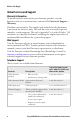
Before You Begin Global Services and Support Warranty Information To understand the warranty for your Intermec product, visit the Intermec web site at www.intermec.com and click Service & Support > Warranty. Disclaimer of warranties: The sample code included in this document is presented for reference only. The code does not necessarily represent complete, tested programs. The code is provided “as is with all faults.
Before You Begin Services Description Service contracts • Ask about an existing contract. In the USA and Canada call 1-800-755-5505 and choose this option 1 or 2 and then choose 3 • Renew a contract. • Inquire about repair billing or other service invoicing questions. Outside the U.S.A. and Canada, contact your local Intermec representative. To search for your local representative, from the Intermec web site, click Contact.
Before You Begin 3 In the Select a Product field, choose the product whose documentation you want to download. To order printed versions of the Intermec manuals, contact your local Intermec representative or distributor.
1 Introduction This chapter describes the EasyLAN Wireless Interface Kit for EasyCoder PF2/4i-, PM4i-, and PX4/6i-series printers.
Chapter 1 — Introduction About These Instructions These instructions describe how to install an EasyLAN Wireless network interface in an EasyCoder PF2i, PF4i, PF4i Compact Industrial, PM4i, PX4i, or PX6i printer and how to connect it to a LAN, WAN, Intranet, or Internet network via a wireless connection. The installation instructions describe how to physically install the interface board in a printer and how to set up the IP address, subnet mask, default router, and name server.
2 Physical Installation This chapter describes how to physically install the EasyLAN Wireless Interface Kit in a PF2/4i-, PM4i-, or PX4/6i-series printer. The installation described in this chapter must only be performed by an authorized service technician. Intermec assumes no responsibility for personal injury or damage to the equipment if the installation is performed by an unauthorized person. Take precautions against electrostatic discharges, for example by wearing grounded bracelets.
Chapter 2 — Physical Installation Step-by-Step Instructions 1 Switch off the printer and disconnect the power cord. 2 Disconnect all communication cables. 3 Remove the cover over the electronics compartment, as described on the pages ahead. The electronic compartment contains wires and components with dangerous voltage (up to 380V). Make sure that the printer is switched off and the power cord is disconnected before the left-hand cover is removed. EasyCoder PF2/4i Printers 4 Open the right-hand door.
Chapter 2 — Physical Installation 8 Remove any optional interface board or blind cover plate fitted on the rear plate. 9 Remove any present EasyLAN Ethernet interface installed in the printer including cables etc. 10 Remove the present rear plate like this: a Loosen but do not remove the two #T20 Torx screws that hold the rear plate and the #T20 Torx screw that holds the rear bottom corner of the CPU board. b Carefully manipulate the rear plate out of the groove in the chassis.
Chapter 2 — Physical Installation 15 Connect the EasyLAN adapter board to the PCI connector (J84) on the CPU board so the hole in the board becomes aligned with the spacer and secure the board with the #T20 Torx screw. 16 Route the antenna cable over the SIMMs on the CPU board towards the rear plate and secure it using the cable clips included in the kit.
Chapter 2 — Physical Installation Cable tie Cable clips Light guide Antenna cable #T20 Torx screw and spacer EasyLAN adapter board Antenna EasyCoder PF2/4i-Series Printer Antenna (packed separately when the EasyLAN Wireless interface is factory-installed) EasyCoder PF2/4i-Series Printer, Rear View EasyLAN Wireless Interface Kit Installation Instructions
Chapter 2 — Physical Installation EasyCoder PM4i Printers 4 Using a #T20 Torx screwdriver, loosen the four screws that holds the cover along the lower left edge of the bottom plate. 5 Remove the four screws that hold the cover to the center section. 6 Pull out the cover so you can disconnect the console cable from the CPU board. 7 Put the cover aside on a soft cloth or similar to avoid scratches. 8 Remove any present EasyLAN Ethernet interface including cables etc.
Chapter 2 — Physical Installation 10 Connect the antenna cable to the radio module, which is factoryfitted on the EasyLAN adapter board, as illustrated below. Support the upper edge of the radio module with a finger while connecting the cable. Adapter board Connect antenna cable here Radio module 11 Remove the #T20 Torx screw that holds the upper/front part of the CPU board to the power supply unit and replace it with the hexagonal spacer included in the kit. Keep the screw.
Chapter 2 — Physical Installation 17 Put back the cover over the electronics compartment. 18 Route the cable from the display unit above the ribbon motor. Connect the cable to connector J50 at the upper front corner of the CPU board. 19 Connect the power cord and switch on the power. 20 Enter Setup Mode and print the test label “Hardware Info” in Fingerprint or “HW” in IPL to see if the printer detects the EasyLAN Wireless interface board.
Chapter 2 — Physical Installation Antenna (packed separately when the EasyLAN Wireless interface is factory-installed) EasyCoder PM4i Printer, Rear View EasyCoder PX4/6i Printers 4 Open the front and right-hand doors. 5 Remove the eight #T10 Torx screws that hold the left-hand cover. 6 Put the cover aside on a soft cloth or similar to avoid scratches.
Chapter 2 — Physical Installation 7 Remove any present EasyLAN Ethernet interface including cables etc. Fit the RJ-45 plug included in the kit into the square hole left by the RJ-45 Ethernet connector. 8 Remove the antenna plug, which is snap-locked into the rear plate. 9 Connect the antenna cable to the radio module, which is factoryfitted on the EasyLAN adapter board, as illustrated below. Support the upper edge of the radio module with a finger while connecting the cable.
Chapter 2 — Physical Installation 13 From the inside of the electronics compartment, insert the antenna connector through the round hole in the rear plate and lock it with the washer and nut on the outside. 14 Fit the antenna to the connector of the antenna cable and bend the hinge so the antenna points straight up. 15 From the outside, insert the thin end of the light guide through the small hole next to the antenna on the rear plate. Press the clear plastic “lamp” in place.
Chapter 2 — Physical Installation Antenna (packed separately when the EasyLAN Wireless interface is factory-installed) EasyCoder PX4/6i Printer, Rear View 14 EasyLAN Wireless Interface Kit Installation Instructions
3 Setup (General) This chapter describes the various ways which you can connect your EasyLAN-equipped printer to your PC, in order to set the network parameters. It also provides information about the default user name and password, which are needed to change the setup parameters.
Chapter 3 — Setup (General) Setting up Network Parameters There are several different ways you can set up your network parameters: • Connect the printer to a PC and run the PrintSet program which can be found on the EasyLAN CD and on the Intermec website. PrintSet requires a PC running Windows 98 or later. This is the easiest and most convenient way to set up your printer. • Fingerprint: Establish a serial (RS-232) communication with the printer and set it up using Fingerprint setup strings or setup files.
Chapter 3 — Setup (General) 3 Set up the printer and the terminal for the communication parameters and type of handshake. 4 Press the key on the printer’s keyboard to check that the printer uses either auto or an RS-232 serial channel as I/O channel. 5 Check that the connection is working. Also refer to your printer’s user’s guide and the Intermec Fingerprint Programmer’s Reference Manual or the IPL Programmer’s Reference Manual.
Chapter 3 — Setup (General) User and Password By default, the user is admin and the password is pass. Initially, this user and password gives unrestricted access to all setup parameters, except Region. Changing the Region requires a special password, which is distributed only to authorized personnel. Use of the EasyLAN Wireless network interface with an incorrect REGION setting may be in violation of applicable laws.
4 Setup in Fingerprint This chapter explains how to set up the wireless network communication in printers running Intermec Fingerprint v8.40 (or later). The only requirement on the PC side is a terminal program that can transmit and receive ASCII characters on an RS-232 line. Thus, this method is recommended when you do not have the opportunity to run the PrintSet program, for example when you are using an operating system other than Windows.
Chapter 4 — Setup in Fingerprint Setting Up Wireless Communications This section describes how to perform some common tasks such as changing user and passwords, as well as setting individual network parameters with Fingerprint commands. General Once a wired serial communication is established, you can use Fingerprint setup strings or setup files to set up the necessary EasyLAN Wireless parameters. All settings are saved in files on the printer flash memory.
Chapter 4 — Setup in Fingerprint Changing User To change the current user in Fingerprint, the “su”command is used. Syntax: RUN"su [-p ] " su requests the password for , and switches to that user after checking the password file. Valid names are admin and user. Everyone can become user even if user’s password is set. No password is requested if the current user already is the one to switch to.
Chapter 4 — Setup in Fingerprint Changing Passwords To change the password for a user in Fingerprint, the “passwd”command is used. Syntax: RUN"passwd []" passwd changes the user’s password. First, the user is prompted for the current password (if it exists). If the current password is correctly typed, a new password is requested. The new password must be entered twice to avoid typing errors. The new password’s total length must be less than 128 characters.
Chapter 4 — Setup in Fingerprint rebooting the printer is the “ACTIVE” setting. Setting this to anything other than a “0” will cause the current settings to be activated. Reading the ACTIVE setting will indicate whether the current settings are being used or not. 0 indicates that the current settings are not active (changes have been made since startup or last non-zero setting of ACTIVE). 1 indicates that the settings are being used.
Chapter 4 — Setup in Fingerprint SSID (Network Name) The SSID (Service Set Identifier) is 0-32 characters used to differentiate wireless LANs that overlap in frequency and physical coverage area. An empty SSID string signifies that the printer will associate with any network. By default SSID is INTERMEC. Non-alphanumeric octets are entered by “%HH” (a percent sign and two hexadecimal digits (0-9, a-f, A-F) representing the value of the character). Example: “12%2034” is equivalent to “12 34”.
Chapter 4 — Setup in Fingerprint Examples: SETUP "wlan","WEP1","0x1138170147" Sets key #1 (WEP 64, hexadecimal) SETUP "wlan","WEP2","abcde" Sets key #2 (WEP 64, alphanumerical) SETUP "wlan","WEP3","0x123456789abcdef0123456789a" Sets key #3 (WEP 128, hexadecimal) SETUP "wlan","WEP4","Manufacturing" Sets key #4 (WEP 128, alphanumerical) SETUP "wlan","WEP2","" Removes key #2 SETUP "wlan",".WEP_KEY","0" Disables WEP SETUP "wlan",".
Chapter 4 — Setup in Fingerprint to cause problems in certain environments, which is why the two other alternatives have been made available. Example: SETUP "wlan","AUTH","SHARED" Shared Key Authentication will be used. The AUTH setting can also be changed via the printer’s homepage, provided the user is logged in as Admin. WPA Note: WPA functionality is only supported by Fingerprint 8.50 or later. WPA (Wi-Fi Protected Access) is compatible with the 802.
Chapter 4 — Setup in Fingerprint SETUP "wlan","WPA_PSK","" Removes the pre-shared key. SETUP GET/WRITE returns an empty string if the key has not been set, and “****” for any pre-shared key regardless of length. Roaming Bias In an environment with several access points, the network adapter may have problems deciding which access point to connect to. In order to make the adapter less inclined to switch access points, it is possible for the admin to change the ROAM setting.
Chapter 4 — Setup in Fingerprint • LEAP: Cisco proprietary EAP type, requiring a Cisco access point. • PEAP: With EAP/MSCHAPv2, EAP/Token Card (static password), or EAP/MD5-Challenge in the tunnel. 802.1x Settings These 802.1x parameters can be configured: • EAP type: TTLS (default), LEAP, or PEAP, and can also be set to OFF to disable 802.1x. When selecting PEAP or TTLS, the inner authentication type will be changed appropriately for the selected EAP type.
Chapter 4 — Setup in Fingerprint • Two Common names (TTLS and PEAP only): Two different common names may be configured. If both are empty, the supplicant will accept certificates regardless of the server certificate’s common name. If the first common name is configured, the common name (CN) of the server’s certificate must match the first common name. If both common names are configured, the server’s certificate must match one of them. The default is “” (accepts any common name).
Chapter 4 — Setup in Fingerprint Examples SETUP "8021x","EAP_TYPE","TTLS|LEAP|PEAP|OFF" Sets preferred EAP type. SETUP "8021x",".EAP_USER","Admin01" Sets logon username to “Admin01”. SETUP "8021x","EAP_PASS","InfoTech" Sets logon password to “InfoTech”. Note: It is not possible for any user to read the EAP_PASS value. SETUP "8021x","TTLS_USER","Manufacturing" Sets TTLS outer name to “Manufacturing”.
Chapter 4 — Setup in Fingerprint SETUP GET "8021x","STATE",A$ Gets the supplicant state: “Disabled”, “Failed”, “Authenticating”, or “Authenticated”. Note: If you start the printer with EAP type set to OFF and then change the EAP type to TTLS, LEAP, or PEAP, you need to reboot the printer for your new settings to take effect. Until you reboot, STATE returns “Disabled.” 802.
Chapter 4 — Setup in Fingerprint SETUP GET "wlan","CHANNEL",A$ gets the current channel in A$. Access Point Information The printer associates with an access point. The read-only setup-variable “AP_MAC” will assume the MAC address of the access point that the printer is currently associated with. If no association has been performed, the value of “AP_MAC” is “00:00:00:00:00:00”. SETUP GET "wlan","AP_MAC",A$ gets the MAC address of the associated access point in A$.
Chapter 4 — Setup in Fingerprint wrong region/domain is set, please contact your Intermec representative immediately. Continued use of the EasyLAN Wireless network interface with an incorrect REGION setting may be in violation of applicable laws. The region setting will not be reset to default, even if a factory default upgrade is performed. The following regulatory domains are implemented: Regulatory Domains Value Countries Allowed Channels FCC (or USA) U.S.
Chapter 4 — Setup in Fingerprint WPA_PSK .REGION USA (FCC) ROAM 1 # CHANNEL 11 # AP_MAC 00:10:40:25:ee:a9 # SIGNAL 49 # SPEED 11 ACTIVE 1 Setting Up Network Parameters In this document, the use of setup strings or setup files are described. Network parameters could also be set via the printer’s built-in keyboard as described in the printer user’s guide.
Chapter 4 — Setup in Fingerprint SETUP"NETWORK,IP SELECTION,DHCP+BOOTP" (default) SETUP"NETWORK,IP SELECTION,MANUAL" SETUP"NETWORK,IP SELECTION,DHCP" SETUP"NETWORK,IP SELECTION,BOOTP" /. However, anybody can change the IP selection method from the printer’s keyboard using the Setup Mode. 1 IP Address If you have selected MANUAL as manual selection method, you can assign a permanent IP address to the printer: SETUP"NETWORK,IP ADDRESS,nnn.nnn.nnn.
Chapter 4 — Setup in Fingerprint 36 EasyLAN Wireless Interface Kit Installation Instructions
5 Setup in IPL This chapter explains how to set up the wireless network communication in printers running IPL v2.40 (or later). The only requirement on the PC side is a terminal program that can transmit and receive ASCII characters on an RS-232 line. Thus, this method is recommended when you do not have the opportunity to run the PrintSet program, for example because you use some other operating system than Windows.
Chapter 5 — Setup in IPL Setting Up Wireless Communications This section describes how to perform some common tasks such as changing user and passwords, as well as setting individual network parameters with IPL commands. General Once a wired serial communication is established, you can use IPL commands to set up the necessary EasyLAN Wireless parameters. All settings are saved in files on the printer flash memory.
Chapter 5 — Setup in IPL Changing Passwords To change the password for a user in IPL, the “passwd”command is used. xp,user,oldpass,newpass,retyped This command changes the user’s password. If the current password (oldpass) is correctly typed, the password will be changed to newpass. The new password must be entered twice to avoid typing errors. The new password’s total length must be less than 128 characters. Numbers, uppercase letters, and metacharacters are encouraged.
Chapter 5 — Setup in IPL SSID (Network Name) The SSID (Service Set Identifier) is 0-32 characters used to differentiate wireless LANs that overlap in frequency and physical coverage area. An empty SSID string signifies that the printer will associate with any network. By default SSID is “INTERMEC”. Non-alphanumeric octets are entered by “%HH” (a percent sign and two hexadecimal digits (0-9, a-f, A-F) representing the value of the character). Example: “12%2034” is equivalent to “12 34”.
Chapter 5 — Setup in IPL Examples: ws,WEP1,0x1138170147 Sets key #1 (WEP 64, hexadecimal) ws,WEP2,Admin Sets key #2 (WEP 64, alphanumerical) ws,WEP3,0x123456789abcdef0123456789a Sets key #3 (WEP 128, hexadecimal) ws,WEP4,Manufacturing Sets key #4 (WEP 128, alphanumerical) ws,WEP2, Removes key #2 ws,.WEP_KEY,0 Disables WEP ws,.WEP_KEY,1 Select WEP key 1 for use in transmission (0-4 accepted).
Chapter 5 — Setup in IPL In addition to the OPEN and SHARED settings, EasyLAN Wireless can also be set to AUTO authenticate. With this setting active, the network adapter will decide what to do. However, this setting has been found to cause problems in certain environments, which is why the two other settings have been made available. Example: ws,AUTH,SHARED Shared Key Authentication will be used.
Chapter 5 — Setup in IPL ws,WPA_PSK,mykey Sets WPA pre-shared key to “mykey”. ws,WPA_PSK, Removes the pre-shared key. Roaming Bias In an environment with several access points, the network adapter may have problems deciding which access point to connect to. In order to make the adapter less inclined to switch access points, it is possible for the admin to change the ROAM setting. ROAM can be set to a value of 1,2, or 3.
Chapter 5 — Setup in IPL run inside an EAP session. • LEAP: Cisco proprietary EAP type, requiring a Cisco access point. • PEAP: With EAP/MSCHAPv2, EAP/Token Card (static password), or EAP/MD5-Challenge in the tunnel. 802.1x Settings These 802.1x parameters can be configured: • EAP type: TTLS (default), LEAP, or PEAP, and can also be set to OFF to disable 802.1x. When selecting PEAP or TTLS, the inner authentication type will be changed appropriately for the selected EAP type.
Chapter 5 — Setup in IPL another certificate in PEM, DER (.der, .cer), or PKCS #12 (.p12, .pfx) format. • Two Common names (TTLS and PEAP only): Two different common names may be configured. If both are empty, the supplicant will accept certificates regardless of the server certificate's common name. If the first common name is configured, the common name (CN) of the server's certificate must match the first common name. If both common names are configured, the server's certificate must match one of them.
Chapter 5 — Setup in IPL To reinstall the default root CA certificate, install /rom/intermec.cer, or remove the /c/ADMIN/root.cer file. Examples ws,EAP_TYPE,TTLS|LEAP|PEAP|OFF Sets preferred EAP type. ws,.EAP_USER,Admin01 Sets logon user name to “Admin01”. ws,EAP_PASS,InfoTech Sets logon password to “InfoTech”. Note: It is not possible for any user to read the EAP_PASS value. ws,TTLS_USER,Manufacturing Sets TTLS outer name to “Manufacturing”.
Chapter 5 — Setup in IPL ws,VALIDATE,ON|OFF Enables validation of the server certificate (TTLS/PEAP only). All variables may be transmitted by means of: wt,[variable name] except EAP_PASS which always returns “****” if configured, CA_CERT which transmits the name of the last certificate authority successfully installed, and DOWNLOAD_CA which does not transmit anything.
Chapter 5 — Setup in IPL /. Active channel and signal strength is shown in the printer’s display window when the key is pressed. 3 Active Channel 802.11b/g operates on a number of different channels, corresponding to different frequencies. The printer scans for a suitable access point and channel. The selected channel can be read from the printer. The readonly setup-variable “CHANNEL” can assume values from 0 up to 14 depending on the region setting.
Chapter 5 — Setup in IPL wt,SPEED Transmits network speed. Region (a.k.a. Regulatory Domain) Some countries and regulatory authorities only allow the use of a subset of the 14 channels specified in the 802.11b/g standard. To make the product world configurable the setup variable “.REGION” is used. The region can only be set by personnel authorized by Intermec. If the wrong region/domain is set, please contact your Intermec representative immediately.
Chapter 5 — Setup in IPL Setting Up Network Parameters You can now disconnect the printer from the PC. You still need to assign an IP address, subnet mask, default router, and name server. This can be done via the printer’s display and keyboard (provided the server support either DHCP or BOOTP (or both). If not, you must rely on wireless communication and use the ARP’n’PING method, which require that there is a working wireless LAN and the printer is inside the coverage area of an access point.
Chapter 5 — Setup in IPL SETUP: NETWORK These menus will only be displayed when an optional EasyLAN interface board is installed. NETWORK: IP SELECTION NETWORK: IP ADDRESS NETWORK: NETMASK NETWORK: DEFAULT ROUTER NETWORK: NAMESERVER NETWORK: MAC ADDRESS IP SELECTION: DHCP+BOOTP PARITY: MANUAL PARITY: DHCP PARITY: BOOTP IP ADDRESS: 192.168.1.79 Read-only NETMASK: 255.255.255.0 Read-only DEFAULT ROUTER: 192.168.1.1 Read-only NAMESERVER: 192.168.1.
Chapter 5 — Setup in IPL 2 If you have chosen either DHCP+BOOTP, DHCP, or BOOTP, press the key and you can read the temporary IP address automatically assigned by the server, for example: IP ADDRESS: 192.168.1.79 3 After having read the IP address, press the key to go on to Netmask parameter or press the key to exit the Setup Mode. Reading the Netmask, Default Router, and Name Server These parameters work in the same way as reading the IP address.
Chapter 5 — Setup in IPL To set an IP address with ARP ‘n’ Ping 1 On the task bar of the host, choose Start > Accessories > Command Prompt. 2 In the Command Prompt, type: arp -s 3 While still using the Command Prompt, use ping to make the printer set the IP address by typing: ping 4 Exit the Command Prompt.
Chapter 5 — Setup in IPL Setting Network Parameters in Manual Mode Note: MANUAL mode is only supported by IPL 2.40 or later. You can use MANUAL mode to assign a static IP address to the printer. To assign network values manually, connect the printer to the serial port on the host PC and open a communications program such as HyperTerminal. Send this command: nn[,m1[,m2]] where: n is the IP address, in the format n.n.n.n, where n is a number in the range 0-255.
6 Accessing the Printer’s Home Page This chapter describes how to access the printer’s home page in order to determine that the network communication works properly.
Chapter 6 — Accessing the Printer’s Home Page Using the Web Browser Start your web browser (in this example Microsoft Internet Explorer) and enter the printer’s IP address in the Address field (for example, http://192.168.237.109).
Chapter 6 — Accessing the Printer’s Home Page The printer’s home page will appear: The EasyCoder PM4i Home Page From the printer’s home page, you can perform a large number of tasks, including changing or setting the IP address, subnet mask, default router, and name server and changing some of the wireless communication parameters. Please refer to the EasyLAN User's Guide on the CD included with the EasyLAN Wireless Interface Kit.
Chapter 6 — Accessing the Printer’s Home Page 58 EasyLAN Wireless Interface Kit Installation Instructions
Worldwide Headquarters 6001 36th Avenue West Everett, Washington 98203 U.S.A. tel 425.348.2600 fax 425.355.9551 www.intermec.