
Technologies Time Clock User Manual


EasyLAN Wireless Interface Kit Installation Instructions 5
Chapter 2 — Physical Installation
Remove any optional interface board or blind cover plate fitted on the
rear plate.
Remove any present EasyLAN Ethernet interface installed in the
printer including cables etc.
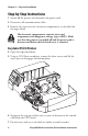
Remove the present rear plate like this:
Loosen but do not remove the two #T20 Torx screws that hold
the rear plate and the #T20 Torx screw that holds the rear bottom
corner of the CPU board.
Carefully manipulate the rear plate out of the groove in the chassis.
Allow the CPU board to flex a little to be able to get the connectors
out of their slots.
Install the rear plate included in the kit in reverse order and tighten all
three screws.
Reinstall any optional interface board or blind cover plate previously
removed.
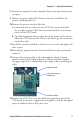
Connect the antenna cable to the radio module, which is factory-
fitted on the EasyLAN adapter board, as illustrated below. Support
the upper edge of the radio module with a finger while connecting the
cable.
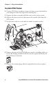
Remove the #T20 Torx screw that holds the upper/front part of the
CPU board to the power supply unit and replace it with the hexagonal
spacer included in the kit. Keep the screw.
8
9
10
a
b
11
12
13
14
Radio module
Adapter board
Connect antenna
cable here