iSPAN™ 5535 PRI PCI ISDN Adapter Users Guide Document No.
NOTE See Appendix I for Regulatory Statements/Conditions that affect the operation of this product. The CE Declaration of Conformity can be found at www.iphase.
Copyright Notice © 2002 by Interphase Corporation. All rights reserved. Printed in the United States of America, 2002. This manual is licensed by Interphase to the user for internal use only and is protected by copyright. The user is authorized to download and print a copy of this manual if the user has purchased one or more of the Interphase adapters described herein. All copies of this manual shall include the copyright notice contained herein.
Assistance Product Purchased from Reseller Contact the reseller or distributor if: • you need ordering, service or any technical assistance • you received a damaged, incomplete or incorrect product. Product Purchased Directly from Interphase Corporation Contact Interphase Corporation directly for assistance with this, or any other Interphase Corporation product. Please have your purchase order and serial numbers ready.
Safety Precautions The following general safety precautions must be observed during all phases of operation of this equipment. Failure to comply with these precautions or with specific warnings elsewhere in this manual violates safety standards of design, manufacture, and intended use of the equipment. Interphase Corporation assumes no liability for the user’s failure to comply with these requirements.
Telephone Lines Unsafe Voltages As unsafe voltages (Telecommunication Network Voltages) exist on ISDN lines, safety precautions must be taken to prevent contact with any dangerous area of the system. WARNING ■ The ISDN cable(s) must remain disconnected from the telecommunications system until the card has been installed in the system.
WARNING This equipment generates, uses, and can radiate electromagnetic energy. It may cause or be susceptible to electromagnetic interference (EMI) if not installed and used in a cabinet with adequate EMI protection.
END-USER LICENSE AGREEMENT FOR INTERPHASE CORPORATION SOFTWARE IMPORTANT NOTICE TO USER–READ CAREFULLY THIS END-USER LICENSE AGREEMENT FOR INTERPHASE CORPORATION SOFTWARE (“AGREEMENT”) IS A LEGAL AGREEMENT BETWEEN YOU (EITHER AN INDIVIDUAL OR SINGLE ENTITY) AND INTERPHASE CORPORATION FOR THE SOFTWARE PRODUCTS ENCLOSED HEREIN WHICH INCLUDES COMPUTER SOFTWARE AND PRINTED MATERIALS (“SOFTWARE”).
responsible for any transportation costs, unless expressly authorized in writing by Seller. This warranty does not cover damage to the Product resulting from accident, disaster, misuse, negligence, improper maintenance, or modification or repair of the Product other than by Seller. Any Products or software replaced by Seller will become the property of Seller. REMEDIES AND EXCLUSIONS.
any provision of this Agreement is held invalid, illegal, or unenforceable, the remaining provisions shall in no way be affected or impaired thereby. All rights in the Software not specifically granted in this Agreement are reserved by Interphase.
1Contents Using This Guide ........................................................................................ vii Audience ............................................................................................... vii Icon Conventions ................................................................................. vii Text Conventions ............................................................................... viii Documentation Updates ........................................................
Connecting directly to the line without a CSU .......................... 18 Connecting directly to the line with an internal CSU ............... 19 Connecting to the line through an external CSU ....................... 20 T1/PRI Cabling .................................................................................... 22 T1 Link Requirements ................................................................... 22 European E1/PRI Line ........................................................................
CHAPTER 6 Setting Up RAS Support Properties Overview................................................................................................63 Accessing Online Help ........................................................................63 Determining RAS Support Parameters .............................................64 CHAPTER 7 Troubleshooting Overview................................................................................................67 Interpreting Adapter LEDs ..................
APPENDIX C Using the LoopTest Utility Overview ............................................................................................... 89 Accessing Online Help ........................................................................ 90 Testing your ISDN Line...................................................................... 90 Displaying and Saving Events ........................................................... 92 Setting the Number of Frames to Send .........................................
APPENDIX G Quick Reference of Common Tasks Overview..............................................................................................115 Index of Common Tasks ...................................................................115 Procedures ...........................................................................................116 APPENDIX H ISDN Technology Overview Overview..............................................................................................
vi Interphase Corporation
2Using This Guide Audience This manual assumes that its audience has a general understanding of computing and networking terminology. If you need more information about this terminology (in addition to what this manual provides), see the following web sites: • ISDN links: http://www.bellcore.com/nic http://www.via-isdn.org http://www.comware.com/telcom/telcolnk.htm • Networking glossary: http://www.ctcnet.com/tips/glossary.
Text Conventions CAUTION The Caution icon brings to your attention those items or steps that, if not properly followed, could cause problems in your machine’s configuration or operating system. WARNING The Warning icon alerts you to steps or procedures that could be hazardous to your health, cause permanent damage to the equipment, or impose unpredictable results on the surrounding environment. Text Conventions The following conventions are used in this manual.
Using This Guide /bin/su is the same as: /bin/su ↵ Return Required user input, when mixed with program output, is printed in bold Courier type. Documentation Updates The latest documentation (in Adobe® Acrobat® pdf) for our current products are available on our WWW site. Interphase recommends our customers visit the web site to verify that they have the latest version of the documentation. 1. Access the following web page: http://www.iphase.com 2.
Driver Updates Driver Updates Contact our Technical Support Department at swlib@iphase.com to determine if updated drivers are available for your product. When contacting technical support, please be sure to provide your name, company name and address, phone number, product name, driver version (if applicable), OS and version (if applicable) and serial number. Providing this information will help speed up our response.
1Introduction 1 Adapter Overview The iSPAN™ PRI (Primary Rate Interface) adapter is a Peripheral Component (PCI) add-on board for PCI-based PCs, servers, and workstations. It enables systems to connect to one or two ISDN primary rate interfaces. The single-PRI version is powered by the IBM® PowerPC™ 403GA 32-bit RISC processor at 33 MHz. The dual-PRI version is powered by the IBM PowerPC 403GCX 32-bit RISC processor at 66 MHz, and combined with a 32-bit/33-MHz PCI interface.
RAS Support Overview RAS Support Overview This adapter supports Microsoft® Remote Access Service (RAS), which enables remote user connections over ISDN lines. RAS enables the transport of TCP/IP, IPX/SPX, and NetBEUI protocols. RAS supports all of the mainstream networking clients, including the following: • Windows for Workgroups • LAN Manager • Windows 95 • Windows NT Workstations • Windows NT Servers • UNIX • Macintosh • NetWare • OS/2-based clients.
Chapter 1: Introduction Figure 1-2. RAS Features Product Features • PCI 2.
Minimum System Requirements • Dual PRI version: – 32-bit RISC processor PowerPC 403GCX @ 66 MHz – 8-MB dual port DRAM memory and 128-KB Flash EEPROM – RAS support for up to 60 B channels and 2 D channels (Europe) or 46 B channels and 2 D channels (United States and Japan) • 32-bit, 33-MHz local bus • HDLC and transparent mode on each B channel • Short PCI form factor (174.63 x 106.68 mm) • Full plug-and-play installation.
Chapter 1: Introduction • CSU (Channel Service Unit) (For more information, see North America T1/PRI Line on page 17). Software Drivers You can install only one iSPAN-PRI PCI ISDN adapter per system. Each adapter requires the following drivers: • WAN adapter driver for Windows NT: the basic driver required to support the adapter • RAS Support: the driver required to support Microsoft Remote Access Service over ISDN. Enables the transport of TCP/IP, IPX/SPX, and NetBEUI protocols over ISDN lines.
Software Drivers The complete iSPAN-PRI software is stored on a single diskette or a CD-ROM included in the adapter package.
2Installing the Hardware 2 Overview You can install the iSPAN-PRI adapter in any suitable PCI expansion slot. To install your adapter, follow these basic steps: 1. Verify that the system meets minimum requirements. 2. Inspect the adapter. 3. Install the adapter in a host expansion slot. 4. Connect the adapter to an MVIP Bus, if required. The tools required are a grounding strap and a #1 Phillips head screwdriver. Both are delivered with the product and are included in the packaging.
Inspecting the Adapter CAUTION The adapter is packed in an antistatic bag to protect it during shipment. Keep the adapter in its protective antistatic bag until you are ready to install it in the host computer. To prevent damage to the adapter due to electrostatic discharge, wear a grounding strap on your wrist or ankle and handle the adapter only by its edges. Do not touch its components or any metal parts other than the faceplate.
Chapter 2: Installing the Hardware Installing the Adapter WARNING Your computer operates at voltages that can be lethal. Follow all cautions and warnings in this installation procedure, both to protect yourself and prevent damage to your computer. Use only tools with nonconductive handles, or tools coated with, covered with, or made with nonconductive materials.
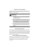
Installing the Adapter 1. Turn off the computer’s power switch, and unplug the unit from its power source. Figure 2-1. Unplugging the Computer 2. Disconnect all cables connected to the main system unit, and remove the computer cover according to the manufacturer’s instructions.
Chapter 2: Installing the Hardware Figure 2-2. Removing the Computer Cover 3. Locate a suitable PCI expansion slot, and remove the screw that attaches the expansion plate to the computer. Save the screw for Step 6. CAUTION If you plan to connect the adapter to an MVIP bus, the location of the adapter depends on the other MVIP adapters. See Connecting the Adapter to an MVIP Bus on page 14 for instructions before proceeding with the installation process.
Installing the Adapter 4. Remove the expansion plate. Figure 2-3.
Chapter 2: Installing the Hardware 5. Carefully remove the adapter from its antistatic bag, and position the adapter in the PCI expansion slot. Align the adapter’s connector pins with the slot’s receptacle; then press gently but firmly on the board to seat it in the slot. 6. Attach the adapter with the screw removed in step 3. Figure 2-4.
Connecting the Adapter to an MVIP Bus NOTE If you need to connect the adapter to other MVIP telephony processing adapters in the cabinet, such as voice, data, fax, video or image processing adapters, and have not already done so, see Connecting the Adapter to an MVIP Bus on page 14. 7. Replace the computer cover. You are now ready to connect the adapter to the appropriate PRI line, as described in Connecting to the Line on page 17.
Chapter 2: Installing the Hardware Requirements for MVIP Bus Electrical Termination For systems with five or fewer MVIP bus connections and less than 90 pF load on the clock lines, it is adequate to place the circuit board that is the master clock source at one end of the cable and electrically terminate the MVIP bus only on the circuit board located at the other end of the cable. NOTE The iSPAN-PRI adapter is generally the master clock source, because it is connected to the network.
Connecting the Adapter to an MVIP Bus How to Configure MVIP Electrical Termination on the iSPAN-PRI The factory default configuration for the iSPAN-PRI adapter does not require jumpers. If the adapter does not have to be electrically terminated, do not insert any jumpers into the 2-pin connectors. If this is the last board in a multiple MVIP bus configuration, the iSPAN-PRI adapter requires electrical termination in the MVIP bus.
3Connecting to the Line 3 Overview The type of line your carrier provides depends on whether you are in North America or Europe. This chapter provides the following information required to connect your adapter to the line: • connection methods and requirements for connecting to a North American T1/PRI line • connection methods and requirements for connecting to a European E1/PRI line • summary of steps to connect the adapter to the network. If you are in North America, continue with the next section.
North America T1/PRI Line If the distance is longer (up to 6200 feet or 1800 meters), you need to connect the adapter in a DS1 configuration. In this configuration, a Channel Service Unit (CSU) must translate the short haul DSX1 interface in order to support the longer distance. The iSPAN-PRI adapter optionally supports an internal CSU. In this case, you can connect the adapter directly to the T1/PRI line, also in a DS1 configuration.
Chapter 3: Connecting to the Line WARNING To avoid harming the WAN, you must first contact your carrier for approval before connecting the adapter to the line. CAUTION In accordance with FCC Rules, Part 68.218 (b), you must notify the telephone company prior to disconnecting the adapter from the line or turning off the power to the adapter’s host system. Without this prior notification, the carrier might temporarily discontinue your T1/PRI service.
North America T1/PRI Line WARNING To avoid harming the WAN, you must first contact your carrier for approval before connecting the adapter to the line. CAUTION In accordance with FCC Rules, Part 68.218 (b), you must notify the telephone company prior to disconnecting the adapter from the line or turning off the power to the adapter’s host system. Without this prior notification, the carrier might temporarily discontinue your T1/PRI service.
Chapter 3: Connecting to the Line WARNING To avoid harming the WAN, you must first contact your carrier for approval before connecting the CSU to the line. CAUTION In accordance with FCC Rules, Part 68.218 (b), you must notify the telephone company prior to disconnecting the CSU from the line or turning the CSU’s power off. Without this prior notification, the carrier might temporarily discontinue your T1/PRI service.
T1/PRI Cabling T1/PRI Cabling WARNING Before connecting the cable, read Telephone Lines Unsafe Voltages in the Safety Precautions section at the front of this manual. The cable between the adapter and the carrier or the CSU must meet standard T1 attenuation and transmission requirements: • 100 Ohm • two twisted pairs, category 3 or higher • maximum length: 655 feet (200 m) without a CSU, 6200 feet (1800 meters) with a CSU.
Chapter 3: Connecting to the Line European E1/PRI Line When you connect the adapter to a European E1/PRI line, first determine the appropriate connection method, cabling requirements, and link requirements. This section describes the method and requirements for connecting the adapter to a European E1/PRI line. Connection Method Generally, your E1/PRI carrier provides a Network Termination 1 (NT1) device to interface between the WAN adapter and the metallic interface of the WAN.
Connector Pinouts The cable must include an RJ48C plug at the end dedicated to the WAN adapter. It must also provide the appropriate plug or cabling system at the end dedicated to the NT1. See Connector Pinouts on page 24 and your NT1 documentation for details. E1 Link Requirements To interoperate successfully, the adapter and the NT1 must be configured with several common E1 settings.
Chapter 3: Connecting to the Line Pin 8 7 6 5 4 3 2 1 Signal 8 Tx out (tip) Tx out (ring) Rx in (tip) Rx in (ring) 1 LEDs 1, 2, 3 & 4 (Port #0) Port #0 (RJ48C) LEDs 5, 6, 7 & 8 (Port #1) RJ48C Pinout Port #1 (RJ48C) Figure 3-4. Adapter’s Faceplate and Connector Pinouts The adapter’s connectors follow the RJ48C specification. Four Light Emitting Diodes (LEDs) display the status of the link (as described in Interpreting Adapter LEDs on page 67).
Connecting the Adapter to the Network 3. Reconnect the power cable and turn on the machine. After connecting the adapter to the network, install the adapter drivers. See Installing the Software on page 27.
4Installing the Software 4 Overview This chapter describes the procedures for installing and setting up your iSPAN-PRI adapter’s software on Microsoft Windows NT 4.0 workstations. This process installs both the basic WAN adapter driver and the RAS Support driver. To install the software, follow these basic steps: 1. Verify that your system meets minimum requirements. 2. Install and set up the drivers. This chapter also explains how to remove the drivers, if required.
Installing and Setting Up the Drivers Installing and Setting Up the Drivers To install and set up the adapter drivers, do the following: 1. Install the WAN and RAS Support drivers. 2. Set up RAS support properties. 3. Set up ISDN B channels. 4. Check the ISDN line with the LoopTest utility.
Chapter 4: Installing the Software Figure 4-1. Network Identification tab of the Network dialog 2.
Installing and Setting Up the Drivers Figure 4-2. Network Adapters tab of the Network dialog 3. Click Add to begin loading the drivers.
Chapter 4: Installing the Software Figure 4-3. Network Adapters List 4. Click Have Disk. The Insert Disk dialog appears, prompting you to insert the disk and identify the file location: Figure 4-4.
Installing and Setting Up the Drivers 5. If you are installing the software from a diskette, insert the diskette, change the installation directory to A:\ and click OK. If you are installing the software from a CD-ROM, insert the CD-ROM. If ‘D:’ is the letter assigned to the CD-ROM drive, change it to D:\5535PRI (or select the appropriate drive) and click OK. The Select OEM Option dialog appears, with 5535 INTERPHASE RAS Support selected: Figure 4-5. Select OEM Option dialog 6.
Chapter 4: Installing the Software Figure 4-6. WAN Adapter Driver Installation 7. If needed, change the default installation path in the Copy To field to the desired pathname. 8. Click Continue to install the driver. The installation program copies product files to the directory specified in the Copy To field, and creates a program group in the Windows NT Start menu.
Installing and Setting Up the Drivers Figure 4-7. WAN Adapters Setup The adapter is automatically detected. The Cards list should be updated to include the iSPAN-PRI adapter (listed as a version of the 5535) in your machine. NOTE If the cards list is empty, the adapter might not be properly installed. Click OK. Then see Problems and Possible Solutions on page 72 for information about correcting the problem.
Chapter 4: Installing the Software 9. Make sure the 5535 adapter is selected in the Cards list of the WAN Adapters Setup dialog. Then do the following to configure the adapter’s ISDN ports: a. Select the port you want to configure (from [0] ISDN PRI to [1] ISDN PRI), and click Properties to display the ISDN PRI Port Properties dialog: Figure 4-8. ISDN PRI Port Properties b. Select the switch type that corresponds to your ISDN subscription, and click OK.
Installing and Setting Up the Drivers 10. When a message informs you that the driver is running, click OK. Figure 4-9. Successful Setup Message To continue the software installation, set up RAS support properties as described in the next section. Setting up RAS Support Properties After you respond OK to the message that the driver is running, the Interphase 5535 RAS Support dialog appears: Figure 4-10. RAS Support Setup This dialog enables you to set up RAS Support properties for the adapter.
Chapter 4: Installing the Software To set up RAS support properties: 1. Click OK to confirm the displayed configuration. – If Remote Access Service is installed on your system, a message informs you that RAS support setup is complete, and states that Remote Access Services (RAS) setup must now be invoked. Click OK to update the ISDN port list in RAS setup. Then skip to Setting Up ISDN B Channels as RAS Ports on page 38.
Installing and Setting Up the Drivers When RAS installation is complete, a message informs you that Remote Access Service has been successfully installed, and reminds you to use Remote Access Admin or User Manager in the Administrative Tools Folder to assign RAS permissions to users. 4. Click OK. To continue the software installation, set up ISDN B channels as RAS ports, as described in the next section.
Chapter 4: Installing the Software The Remote Access Setup dialog appears, with the ISDN port included in the RAS port list: Figure 4-13. Remote Access Setup 2. Select the port and click Configure to set up its connection mode. The Configure Port Usage dialog appears: Figure 4-14. Configure Port Usage 3. Select a port usage option, and click OK.
Installing and Setting Up the Drivers The Remote Access Setup dialog reappears (see Figure 4-13 on page 39). It now shows one ISDN channel configured as a RAS port. 4. To quickly configure all ISDN channels with the same port usage as the first ISDN channel: a. Click Clone until a message informs you there are no more ports of the specified type to clone. b. Click OK. 5.
Chapter 4: Installing the Software Figure 4-15. Network Configuration On this dialog, you can select the Enable Multilink option to allow multiple ISDN B channels to make one logical network connection. This function aggregates several ISDN B channels to increase the bandwidth of PPP links. For more detailed network configuration information, see Microsoft’s online help for RAS. b. Click OK to confirm your network configuration. c. When the Remote Access Setup dialog reappears, click Continue.
Installing and Setting Up the Drivers 6. The INTERPHASE 5535 RAS ISDN support adapter now appears in the Network Adapters list on the Adapters dialog: Figure 4-16. Network Adapters List 7. Click Close to complete the software installation. After the software is fully installed, a message informs you that you must shut down and restart your computer before the settings take effect.
Chapter 4: Installing the Software CAUTION If a Windows NT Service Pack was installed on the system after the first Windows NT installation, you must reinstall it before restarting the computer. For installation information, see the latest available version of your Service Pack help. If you do not reinstall the Service Pack, the Remote Access Service will probably fail to start, or will not behave correctly when connecting ISDN lines.
Installing and Setting Up the Drivers To check the IDSN line using LoopTest: 1. Before executing LoopTest, and to avoid incoming call conflicts, disable the RAS Server, as follows: a. From the Start menu, select Programs, then Administrative Tools (Common), and then Remote Access Admin. The following dialog appears: Figure 4-17. Remote Access Admin Dialog b. From the Server menu, select Stop Remote Access Service. 2.
Chapter 4: Installing the Software Figure 4-18. LoopTest Dialog 3. Select the port number to test (if your adapter has two PRI ports), and enter your local ISDN number. 4. Click Test. The LoopTest Utility normally finishes with the message Test passed in the Diagnostic field. If the Test passed message does not appear, make sure that the ISDN number you entered is correct. For more information about the LoopTest utility and its diagnostics, see Using the LoopTest Utility on page 89. 5.
Removing the Drivers c. If Windows NT does not display the server name automatically, enter the server name preceded by two backslashes (\\). To determine the server name, see Index of Common Tasks on page 115. d. Click OK. To use the adapter in the RAS environment (RAS Server or RAS Dial-Up Networking), see the following: • For an overview, see Index of Common Tasks on page 115. • For detailed information, see Microsoft RAS online help.
Chapter 4: Installing the Software Figure 4-19. Network Adapters List 3. Select INTERPHASE 5535 RAS ISDN support (for the iSPAN-PRI), and click Remove. A warning message informs you that this action will permanently remove the component, and asks if you want to continue. 4. Click Yes to continue the driver removal.
Removing the Drivers The Interphase WAN Adapters driver dialog identifies the install path that will be deleted, and asks if you are sure you want to deinstall the software: Figure 4-20. Uninstallation Main Dialog 5. Click Continue to deinstall the WAN Adapters driver. 6. Confirm your choice by clicking Yes when a pop-up asks you to confirm the card(s) removal and driver deletion.
Chapter 4: Installing the Software 8. If the iSPAN-PRI adapter was the only RAScapable device, a setup message informs you that you have an invalid RAS configuration. It also reminds you to configure RAS and add ports using the Network option in the Control Panel after restarting the system. Click OK to complete the driver deletion. NOTE When the system boots up again, the Remote Access Service will fail to initialize. (As a result, RAS errors will appear in the Windows NT Event Viewer).
Removing the Drivers 50 Interphase Corporation
5Setting Up WAN Firmware and Hardware 5 Overview The WAN Adapter Setup utility enables you to manage hardware and firmware for all Interphase WAN adapters. Use this utility to add and remove Interphase WAN adapters and their firmware, and to manage ISDN properties for adapter ports.
Managing Firmware and Hardware Managing Firmware and Hardware NOTE The iSPAN-PRI is listed as the 5535 adapter in WAN Adapter Setup dialogs. Start the WAN Adapter Setup utility in either of the following ways: • From the Start menu, select Settings, and then Control Panel. Then double-click the WAN Setup icon. • From the Start menu, select Programs, then INTERPHASE WAN Adapters, and then WAN Setup.
Chapter 5: Setting Up WAN Firmware and Hardware Figure 5-1. WAN Adapters Setup The WAN Adapters setup dialog has two sections: • The Microcode section is for firmware management. • The Cards section is for hardware management. Firmware Management The Microcode section of the Wan Adapter Setup dialog displays firmware information for the currently-selected WAN adapter. It displays the protocols you can use with the adapter, and their status.
Managing Firmware and Hardware The firmware status is represented by a general LED color for the microcode and individual LEDs for each protocol, as follows: LED Color For General LED Red No microcode is found on the N/A disk for the current card. Gray Microcode is found but is not loaded into the card. The protocol is inactive. Yellow Microcode is running on the card but is different from that found on the disk for this card. N/A Green The microcode is running. The protocol is active.
Chapter 5: Setting Up WAN Firmware and Hardware Use the following buttons to set up microcode information: Click... To do this... Load Download the current microcode to the selected adapter. CAUTION CAUTION: This option disconnects all current RAS-connected users and disables the RAS Server. After a microcode download, the RAS Server must be re-enabled, as follows: 1. From the Start menu, select Programs, then Administrative Tools (Common), and then Remote Access Admin. 2.
Setting Up ISDN PRI Port Properties Microcode section displays firmware information for the adapter selected in the Cards section. You can use the buttons in this section to add, remove, or configure WAN adapters. The adapter status is represented by its icon color: LED Color Meaning Gray The adapter is detected but is not working. Yellow The hardware configuration has been changed but not applied. Green The adapter is running. Use the following buttons to set up adapter hardware: Click...
Chapter 5: Setting Up WAN Firmware and Hardware Use the ISDN PRI Port Properties dialog to view and set the ISDN port switch type (and, for Europe, the CRC type). To display the ISDN PRI Port Properties dialog: 1. Select the ISDN port you want to configure in the Cards section of the WAN Adapters setup dialog (shown in Figure 5-1 on page 53.) 2. Click the Properties button in the Cards section: The ISDN PRI Port Properties dialog appears: Figure 5-2.
Setting Up ISDN PRI Port Properties ISDN 2) standard (sometimes referred to as National). Select AT&T CUSTOM if your telephone company uses an AT&T 5ESS Custom switch. All of these switch types offer T1/PRI access (also called 23B+D). • In Europe, select ETSI EUROISDN. This switch type offers E1/PRI access (also called 30B+D). Selecting the CRC Type (Europe Only) If your location is Europe, you also need to select the CRC type in the ISDN PRI Port Properties dialog (shown in Figure 5-2 on page 57).
Chapter 5: Setting Up WAN Firmware and Hardware NOTE The Edit DS1 Properties button is enabled only when an American Switch Type is selected. The DS1 Properties dialog appears: Figure 5-3. DS1 Properties Line framing, CRC, and Line code parameters describe physical level parameters, which cannot be modified on a PRI Line.
Setting Up ISDN PRI Port Properties The following table describes DS1 options that can be edited: Option Description Activate the CSU This option depends on whether the connection between the adapter and the T1 line requires a CSU: • Select Activate the CSU to activate a CSU between the network and the adapter. The CSU is included on the iSPAN-PRI adapter. However, to activate the CSU you must purchase the CSU option. (An external CSU is not required).
Chapter 5: Setting Up WAN Firmware and Hardware Option Description Facility Data Link Facility Data Link protocols are used to exchange Protocol(s) messages between the adapter and the remote end of the network. Such messages are issued by the Telco to put the adapter in loopback mode for testing when problems occur. They are also used to transmit statistics about physical transmission errors on the line. Two protocols are available for the facility data link: the ANSI-T1-403 and the ATT-54016 protocol.
Setting Up ISDN PRI Port Properties 62 Interphase Corporation
6Setting Up RAS Support Properties 6 Overview The RAS Support Setup utility enables you to set up an inactivity timer for ISDN connections and determine RAS Support parameters for the adapter. The chapter explains how to do the following Ras Support Setup tasks: • Access online help • Determine RAS Support parameters Accessing Online Help For detailed information about the functions described in this chapter, see the RAS Support Setup online help.
Determining RAS Support Parameters Determining RAS Support Parameters You can use the RAS Support dialog to determine the network name of the adapter and set a timeout limit for adapter ports. NOTE The iSPAN-PRI is listed as the 5535 in RAS Support Setup dialogs. To access the RAS Support Setup dialog: 1. From the Start menu, select Settings, and then Control Panel. 2. Double-click the Network icon, and then select the Adapters tab. 3.
Chapter 6: Setting Up RAS Support Properties The following table describes the parameters in the 5535 RAS Support dialog fields: Parameter Function Adapter Identifies the status and the network name of the adapter. The LED beside the adapter name represents the adapter status. Green means that the driver is running, and gray means that it is not running. The numeric suffix in the name (in this case, 3) is the logical network adapter number assigned by Windows NT.
Determining RAS Support Parameters 66 Interphase Corporation
7Troubleshooting 7 Overview This chapter provides possible solutions for common problems you might encounter while installing and operating your adapter. Before proceeding with troubleshooting, make sure you have carefully followed the steps for installing and setting up the hardware and the software, and have rebooted the system. Also, check the system log to see what kind of errors, if any, are being recorded.
Interpreting Adapter LEDs LED functions differ depending on whether the adapter is configured to operate in North America (with T1/PRI access), in European countries other than France (with E1/PRI access and CRC4), or in France (with E1/PRI access and no CRC type). North America In North America, the adapter LEDs for each port function are as follows: LED Color Meaning if the light is ON... 1 Green Clock is synchronized. 2 Green Physical layer is active.
Chapter 7: Troubleshooting The following table describes the adapter status when the sequence of LEDs appears as follows: LED1 LED2 LED3 LED4 Meaning On On Off Off Adapter is operational. On On On Off A synchronization problem occurred on the ISDN carrier side. Off Off Off On No power is detected on the line. Make sure cable is plugged in correctly. Off Off Off Off Your ISDN provider is currently sending an AIS alarm to the adapter.
Interpreting Adapter LEDs The following table describes the adapter status when the sequence of LEDs appears as follows: LED1 LED2 LED3 LED4 Meaning On On Off Off Adapter is operational. On Off On On Your E1/PRI line does not support CRC4 functionality. Deselect the CRC4 option. (See Setting Up ISDN PRI Port Properties on page 56.) On Off On Off Remote Alarm Indication (RAI). Your ISDN provider has synchronization problems and is reporting this problem to you.
Chapter 7: Troubleshooting In their operational state, the LEDs must be as follows: LED Color State must be... 1 Green On 2 Green On 3 Yellow Off 4 Red Off The following table describes the adapter status when the sequence of LEDs appears as follows: LED1 LED2 LED3 LED4 Meaning On On Off Off Adapter is operational. On Off On Off Your E1/PRI line requires CRC4. Select the CRC4 option. (See Setting Up ISDN PRI Port Properties on page 56.
Problems and Possible Solutions Problems and Possible Solutions Problem Possible Solution(s) Adapter is not detected during software installation This problem occurs if the system does not detect the adapter after the setup program copies driver files to the installation directory. (That is, the cards list is empty on the WAN Adapter Setup dialog, as described on page 33 of Installing the Software.) When a message tells you to add a card: 1. Click OK. 2.
Chapter 7: Troubleshooting Problem Possible Solution(s) Computer does not boot up or Host adapter not found Your PCI bus automatically configures the hardware resources used by the adapter. Therefore, a resource conflict (address or IRQ) is probably not the problem. To resolve the problem: 1. Check to see whether the adapter is properly seated in the PCI slot. 2. Try a different PCI slot. 3. Contact Interphase Technical Service. LoopTest failed 1.
Problems and Possible Solutions Problem Possible Solution(s) Remote station failed to connect to the RAS Server If you do not know how to check the following items, see Index of Common Tasks on page 115: 1. Use the Event Viewer from Windows NT Administrative Tools to see if the Remote Access Service is successfully initialized. 2. Make sure at least one ISDN RAS port is allowed to accept incoming calls. 3.
Chapter 7: Troubleshooting Problem Possible Solution(s) RAS initialization failed in the driver-event log Look up the failure cause in your Microsoft RAS documentation. No valid configuration message in SynWatch configuration panel 1. Check whether the adapter and the associated drivers are installed correctly. (See Index of Common Tasks on page 115.) CSU activation failed at load time 2. In the WAN Adapter Setup program, check that the ISDN Layer is present in the adapter microcode.
Problems and Possible Solutions 76 Interphase Corporation
ASpecifications A Adapter Specifications Item Specification Host Bus Interface PCI Local Bus Revision 2.1 PCI Form Factor Length: 174.6 mm Width: 106.7 mm Depth: 17.2 mm Host Data Transfer Adapter with 2 PRI ports: 8MB dual port DRAM Adapter with 1 PRI port: 4MB dual port DRAM Optional Functions 32-bit, 33-MHz local bus Operating Power 1.3A maximum @ 5.
Storage Environment Storage Environment This section assumes the adapter is stored in its original antistatic bag and box.
BUsing the SynWatch Utility B Overview The SynWatch utility is a protocol analyzer that enables you to watch frames exchanged between the adapter and the ISDN network. This powerful utility helps you track communication establishment on the ISDN D channel, as well as data traffic on ISDN B channels. Each ISDN channel has a stand-alone configuration, and can be selected or deselected. SynWatch provides diagnostics for ISDN connection failures.
Accessing Online Help Accessing Online Help For detailed information about the functions described in this appendix, see the SynWatch online help. You can access online help in the following ways: • Use the menu command Help to display the main online help. • Press F1 to display contextual help in a pop-up window. • Move the cursor over a window control to display a pop-up with the name of the control. Starting SynWatch NOTE The iSPAN-PRI is listed as the 5535 adapter in SynWatch dialogs.
Appendix B: Using the SynWatch Utility Figure B-1. Main SynWatch dialog The main SynWatch dialog has two sections: • The left side is the configuration panel. It displays the adapter description. The configuration panel is used to activate or deactivate frame watching. • The right side is the monitor panel. It displays exchanged frames.
Mouse Button Functions Mouse Button Functions Synwatch manages configuration panel mouse clicks as follows, depending on whether the ISDN channel is selected or deselected. Left-click the checkbox beside the channel to activate or deactivate frame watching for that channel. To select or deselect all of a port’s channels, leftclick the checkbox beside the port. To select or deselect all of an adapter’s ports, left-click the checkbox beside the adapter.
Appendix B: Using the SynWatch Utility the ISDN connection phase. For example, if a RAS connection fails (during either dial-in or dial-out), the first channel to watch is the ISDN D channel. To activate watching on an ISDN D channel: 1. Select the channel in the configuration panel of the Synwatch dialog. A list of watch modes appears: Figure B-2. ISDN D Channel Watch Modes 2. To activate frame logging, select one of the watch modes: – Select LAPD to see detailed descriptions of signalling frames.
Watching ISDN Channels Watching ISDN B Channels NOTE Before establishing a call, you cannot know which ISDN B channel will be used. Therefore, to be sure to capture call data, you must activate traces for all the ISDN channels. ISDN B channels are used to transmit data frames after an ISDN connection is established. The first few data frames exchanged between local and remote sites correspond to a second connection phase to allow the establishment of the upper layer (for example, the PPP protocol). 1.
Appendix B: Using the SynWatch Utility 2. To activate frame logging for the selected channel or port, select one of the watch modes (RAS uses the PPP Protocol): – X25 – PPP – Frame Relay – SDLC – QLLC – Hexadecimal Dump For detailed information about each watch mode, see SynWatch online help. Watching ISDN Layer 1 Alarms ISDN Layer 1 alarms are managed by the adapter, and are activated when physical events occur. To display these alarms using SynWatch: 1.
Stopping and Freezing the Display Stopping and Freezing the Display To stop watching channels and discard frame information, do the following: To stop watching… Deselect this… A channel the channel in the configuration panel. All of a port’s channels the port in the configuration panel. All of an adapter’s ports the adapter in the configuration panel. When you stop watching channels by deselecting the channel, port, or adapter, SynWatch discards all frame information for the affected channel(s).
Appendix B: Using the SynWatch Utility only an ISDN disconnection. Changing to LAPD displays more details about the cause of the disconnection (for example, user busy or user not responding). Changing the watch mode is also useful if you are watching an ISDN frame in Hexa Dump mode while PPP frames are being exchanged. Reinterpreting associated information in PPP Protocol mode makes this information more meaningful and easier to read.
Saving and Editing Frames Figure B-4. ISDN Channel Settings 3. Choose the font and/or color(s) you want to use for this channel, and click OK. SynWatch updates the monitor panel with your new settings immediately. Saving and Editing Frames You can use the SynWatch Save option to save all frame information recorded in the monitor panel as an ASCII (text) or binary file. You can read a text file using any text editor, but SynWatch cannot read or reinterpret the text file.
CUsing the LoopTest Utility C Overview The LoopTest utility enables you to check your ISDN line quickly and easily. It checks for electrical problems, hardware connectivity, and ISDN compatibility problems. LoopTest also tests the adapter’s ISDN line by establishing 2 ISDN B channels in a loopback connection. One channel is set up to accept incoming calls, and the other channel calls the first channel.
Accessing Online Help Accessing Online Help For detailed information about the functions described in this appendix, see the LoopTest online help. You can access online help in the following ways: • Use the Help menu command to display the main online help. • Press F1 to display contextual help in a pop-up window. • Move the cursor over a window control to display a pop-up with the name of the control. Testing your ISDN Line To check your ISDN line, do the following: 1.
Appendix C: Using the LoopTest Utility 2. From the Start menu, select Programs, then INTERPHASE WAN Adapters, and then LoopTest. The main LoopTest dialog appears: Figure C-2. LoopTest main dialog 3. Select the port to test from the drop-down list (if your adapter has two PRI ports), and enter your own ISDN number. 4. Click Test. The diagnostic field describes the test result. If the message Test Passed appears, your ISDN line is working and RAS dial-in or dial-out can be done.
Displaying and Saving Events NOTE If you want to test more than two B channels or more than one port simultaneously, launch several instances of the utility and repeat steps 2 to 4 for each channel or port. (You can change the number of frames sent if you want a longer test—see Setting the Number of Frames to Send on page 93). 5. To re-enable the RAS Server: a. From the Start menu, select Programs, then Administrative Tools (Common), and then Remote Access Admin. b.
Appendix C: Using the LoopTest Utility 1. Access the LoopTest main dialog, as described in steps 1 and 2 of Testing your ISDN Line on page 90. 2. Select Display event list from the Test menu. To save the event list to an ASCII (text) file, selecting Save or Save as (to save a previously saved file with a different name) from the Test menu. Setting the Number of Frames to Send You can set the number of frames you want LoopTest to send during communication. To set the number of frames to send: 1.
Understanding LoopTest Messages Understanding LoopTest Messages The Diagnostic field in the main LoopTest dialog displays LoopTest test results: Figure C-4. LoopTest Main Dialog The following table describes diagnostic messages: Message Cause Test passed LoopTest detected no errors during testing. Card missing or non-ISDN An error occurred before accessing the network. Possible causes are: • The adapter is not installed. • The drivers are not properly installed.
Appendix C: Using the LoopTest Utility Message Cause Driver Not Loaded The adapter driver was not in a working state when LoopTest was launched. Possible causes are: • The adapter is not installed. • The driver is not installed, or is improperly installed. • The firmware is invalid (ISDN layer not present) or not loaded. To check the firmware status: a. From the Start menu, select Programs, then INTERPHASE WAN Adapters, and then WAN Setup. b.
Understanding LoopTest Messages Message Cause Test failed The connection between the two ISDN B channels could not be established before time-out because another application answered the call. The Remote Access Server was probably running when the test started. To restart the test: 1. From the Start menu, select Programs, then Administrative Tools (Common), and then Remote Access Admin. 2. From the Server menu, select Stop Remote Access Service. 3.
DUsing RAS Utilities D Overview To improve Microsoft Remote Access Service features, several RAS utilities have appeared on the market. This appendix provides a general description of the following popular RAS utilities: • RAS Manager • RasTracker • Routing and Remote Access Service (RRAS) RAS Manager RAS Manager, from NTP Software, is a client/server application that provides full-time control, real-time monitoring, and session-by-session accounting for RAS connections on a user-by-user basis.
RasTracker For more information about RAS Manager, see the following web site: www.ntstorage.com RasTracker RasTracker, from Northern Technologies, is a client/server application that works in real-time to provide you a constantly accurate view of the use of resources. RasTracker logs all actions so that you can monitor which ports are used, when, by which accounts.
Appendix D: Using RAS Utilities • An easy, intuitive, remotable graphical user interface and command line interface with scripting • APIs for third party routing protocols, user interface, and management • Demand-dial routing • PPTP server-to-server for secure Virtual Private Networks • RADIUS client support For more information about RRAS, see the following web site: www.microsoft.
Routing and Remote Access Service 100 Interphase Corporation
EUsing the LineTest Utility E Overview CAUTION The LineTest utility should be used only in cases of trouble at installation, and only with Telco agreement. When an adapter port is working properly, it is in Operational mode. The LineTest utility enables you to set port modes so that you can do low-level testing.
Determining the Current Port Mode Determining the Current Port Mode NOTE The iSPAN-PRI is listed as the 5535 in LineTest utility dialogs. To determine the port’s current mode: 1. From the Start menu, select Programs, then INTERPHASE WAN Adapters, and then LineTest. The main LineTest dialog appears. Figure E-1. LineTest Dialog On this dialog, animated port icons and a text message provide a continuously updated status of the port mode.
Appendix E: Using the LineTest Utility 2. Click Select mode to display the Port Test Configuration dialog. Figure E-2. Port Test Configuration Dialog 3. Select the appropriate port or clock mode for your testing or operating needs. The following sections provide detailed information about setting these modes.
Setting Port and Clock Modes Loopback Mode Loopback mode is a transmission state in which the signal received by the port is returned to the sender. Use this mode when the remote end (the Telco, for example) is testing your line; all information sent is returned to the remote end. To select this mode, select Loopback mode on the Port Test Configuration dialog (shown in Figure E-2 on page 103).
Appendix E: Using the LineTest Utility Figure E-3. Port Options dialog 2. Select the LoopTest setting you want to use. PRBS Generator and Monitor Mode The PRBS Generator and Monitor mode causes a port to generate and transmit Pseudo Random Bit Sequences online while it tries to synchronize on the received signal. CAUTION Use this mode only with Telco agreement. Also, when you use this mode, make sure that remote equipment is set to loopback mode.
Setting Port and Clock Modes When this mode is selected, the text message portion of the LineTest main dialog displays the following synchronization results: Message Meaning No error The receiving bit sequences completed, and the port found no errors when comparing sent and received bit sequences. X bits in error/sec The port is comparing received bit sequences with sent bit sequences. Each erroneous bit found is added, and the sum is displayed each second.
Appendix E: Using the LineTest Utility In such configurations, the clock of the local port must be in slave mode, and the clock of the remote adapter must be in master mode (which is the default clock type). To set the clock mode: 1. Click Options on the Port Test Configuration Dialog (shown in Figure E-2 on page 103). The Port Options dialog appears: Figure E-4. LineTest Options dialog 2. Select the clock setting you want to use.
Setting Port and Clock Modes 108 Interphase Corporation
FUsing the LineStatus Utility F Overview The LineStatus utility enables you to see what's wrong when a problem occurs with your network adapter (for example, if you cannot connect to a remote site or if no one can connect to your host). This appendix explains how to do the following: • access online help • interpret alarm, error, loopback, and statistics information. Accessing Online Help For detailed information about the functions described in this appendix, see the LineStat online help.
Interpreting LineStatus Indicators Interpreting LineStatus Indicators NOTE The iSPAN-PRI is listed as the 5535 in the LineStatus dialog. The LineStatus dialog displays LEDs and statistics about each adapter port. It notifies you of alarms, errors, loopback mode, and statistics related to the port. When a port is operating under normal conditions, all LEDs are grey. To view LineStatus information: 1. From the Start menu, select Programs, next INTERPHASE WAN Adapters, and then LineTest.
Appendix F: Using the LineStatus Utility Alarm LEDs The following alarm LEDs indicate connection problems that result from line failures: LED Meaning LOS Loss of Signal. Typically appears when no electrical signal is detected. (check if line is plugged on the adapter and on the network interface). LOF Loss of Frame (also known as Red Alarm) appears when many frames are lost because of framing errors. The terminal is unable to synchronize on the DS1 signal.
Interpreting LineStatus Indicators Error LEDs The following error LEDs indicate port error events that generate communication problems: LED Meaning BPV BiPolar Violation. For an AMI-coded signal, the occurrence of a pulse of the same polarity as the previous pulse causes a BPV error event. PCV Path Coding Violation. • In D4 and E1-nonCRC formats, a frame synchronization bit error. • In ESF and E1-CRC formats, a CRC error. CS Controlled Slip.
Appendix F: Using the LineStatus Utility Statistics Parameters The following statistics fields display performance parameters accumulated during the last 24 hours the interface is running: Parameter Meaning Uptime Length of time that the interface has been running. UnAvailable Seconds (Also known as UAS). Number of seconds that the interface is unavailable. The DS1 interface is considered unavailable from the onset of 10 contiguous SESs, or the onset of the condition leading to a failure.
Interpreting LineStatus Indicators 114 Interphase Corporation
GQuick Reference of Common Tasks G Overview This section explains how to complete common tasks associated with the iSPAN-PRI adapter. For more detailed information about RAS tasks, see your RAS documentation. Index of Common Tasks For information about how to… See page... Determine which version of Windows NT Service Pack is installed. 116 Determine the server name needed to start the Remote Access Server. 116 Know which adapter’s port is used when calling with an ISDN RAS port.
Procedures For information about how to… See page... Enable IPX or IP routing. 121 Allow a remote user to set a specific IP address. 122 Supply an IP address from a static address pool to a remote user. 123 Disconnect an ISDN port automatically when no data traffic occurs after a specified length of time. 124 Procedures NOTE The iSPAN-PRI is listed as the 5535 in software dialogs. If you want to... Do this... Determine which version of the Windows NT Service Pack is installed 1.
Appendix G: Quick Reference of Common Tasks If you want to... Do this... Know which adapter’s port is used when calling with an ISDN RAS port Note the following (assuming that the iSPAN-PRI is the only ISDN RAS-capable device): See if the drivers are running 1. From the Start menu, select Programs, then Administrative Tools (Common), and then Event Viewer.
Procedures If you want to... Do this... Open Remote Access Setup 1. From the Start menu, select Settings, and then Control Panel. 2. Double-click the Network icon, and select the Services tab to display the Services dialog: 3. From the Network Services list, select Remote Access Service, and then click Properties. Figure G-1. Remote Access Setup Bind a protocol to an ISDN RAS Port 1. Open the Remote Access Setup dialog. (See Open Remote Access Setup on page 118). Then click Network.
Appendix G: Quick Reference of Common Tasks If you want to... Do this... Configure a RAS port to accept incoming calls 1. Open the Remote Access Setup dialog. (See Open Remote Access Setup on page 118). Then click Configure. 2. Enable either the Receive calls only or the Dial out and Receive calls option. 3. Confirm your choice by clicking OK. Configure a RAS port to dial out 1. Open the Remote Access Setup dialog. (See Open Remote Access Setup on page 118). Then click Configure. 2.
Procedures If you want to... Do this... Configure a multilink connection The Multilink PPP protocol aggregates several ISDN B channels to increase the bandwidth of PPP links. To enable this option, do the following: 1. In the Network configuration: a. From the Start menu, select Settings, and then Control Panel. b. Double-click the Network icon, and select the Services tab to display the Services dialog. c. From the Network Services list, select Remote Access Service, and then click Properties. d.
Appendix G: Quick Reference of Common Tasks If you want to... Do this... Enable IPX routing The RIP for NWLink IPX Service must be installed in the Windows NT Network Services list. 1. From the Start menu, select Settings, and then Control Panel. 2. Double-click the Network icon, and select the Protocol tab. 3. From the protocols list, select NWLink IPX/SPX Compatible Transport, and then click Properties. 4. Select the Routing tab, and enable the Enable RIP Routing option.
Procedures If you want to... Do this... Allow a remote user 1. From the Start menu, select Settings, and then to set a specific IP Control Panel. address 2. Double-click the Network icon, and select the Services tab. 3. From the services list, select Remote Access Service, and then click Properties. 4. In the Remote Access Setup dialog, click Network. 5. In the Network dialog, click the TCP/IP Configure button. 6.
Appendix G: Quick Reference of Common Tasks If you want to... Do this... Supply an IP address from a static address pool to a remote user 1. From the Start menu, select Settings, and then Control Panel. 2. Double-click the Network icon, and select the Services tab. 3. From the services list, select Remote Access Service, and then click Properties. 4. In the Remote Access Setup dialog, click Network. 5. In the Network dialog, click the TCP/IP Configure button. 6.
Procedures If you want to... Do this... Disconnect an ISDN port automatically when no data traffic occurs after a specified length of time 1. From the Start menu, select Settings, and then Control Panel. 2. Double-click the Network icon, and select the Adapter tab. 3. From the adapter list, select INTERPHASE 5535 RAS ISDN support, and then click Properties. 4. On the RAS Support dialog, enter an idle time-out value in the Idle Timeout field.
HISDN Technology Overview H Overview Integrated Services Digital Network (ISDN) is an internationally agreed-upon standard for end-to-end digital communications over the public switched network. ISDN includes specifications for signalling, long-distance transmission, bulk subscriber lines, and individual subscriber lines.
Primary Rate Interface Each ISDN B channel can be used separately to allow two different connected users at the same time. The ISDN B channels can also be combined to provide a total bandwidth of 128 Kbps. Primary Rate Interface The ISDN Primary Rate Interface, like BRI, has one D channel, but it has more than two B channels. The number of B channels for PRI differs from the United States to Europe. • In the United States and Japan, PRI consists of 24 digital channels: one D channel and 23 B channels.
IRegulatory Statements I FCC iSPAN-PRI FCC Part 15 Regulatory Compliance This equipment has been tested and found to comply with the limits for a Class A digital device, pursuant to part 15 of the FCC Rules. These limits are designed to provide reasonable protection against harmful interference when the equipment is operated in a commercial environment.
FCC An FCC compliant telephone cable and modular plug are provided with this equipment. This equipment is designed to be connected to the telephone network or premises wiring using a compatible modular jack, which is Part 68 compliant. This equipment cannot be used on telephone companyprovided coin service. Connection to Party Line Service is subject to state tariffs.
Appendix I: Regulatory Statements Canada Industry Canada CS-03 Notice The Industry Canada label identifies certified equipment. This certification means that the equipment meets certain telecommunications network protective, operational and safety requirements as prescribed in the appropriate Terminal Equipment Technical Requirements document(s). The Department does not guarantee the equipment will operate to the user’s satisfaction.
Canada • The Ringer Equivalence Number: not applicable to the Model 5535_2PRI_MVIP device. Notice: The Ringer Equivalence Number (REN) assigned to each terminal device provides an indication of the maximum number of terminals allowed to be connected to a telephone interface. The termination on an interface may consist of any combination of devices subject only to the requirement that the sum of the Ringer Equivalence Numbers of all the devices does not exceed 5.
Appendix I: Regulatory Statements Europe Regulatory Information for Europe This equipment displays the CE 165 X mark to show that it has been tested and found to be in full compliance with the requirements of the Terminal Equipment, EMC and Low Voltage Directives (91/263/EEC, 89/336/EEC and 72/23/EEC, as amended by Directive 93/68/EEC).
EN60950–IEC950 Security Standard EN60950–IEC950 Security Standard This equipment complies with the EN60950–IEC950 security standard, with the following restrictions: • The modem card must be used only in a data terminal equipment (DTE)—for example, a computer—with a screw-down cover or lid. Because unsafe voltages (TNV) exist on the modem card, disconnect the modem card from the telephone line while the cover (lid) of the DTE (computer) is removed.
Glossary 2B+D ◆ See BRI. ◆ See PRI. 30B+D ◆ See PRI. 802.2 IEEE ◆ Standards that govern the LLC within the Data Link layer of the OSI model. LLC frames carry user information between the nodes on a network and define the transmission of a frame between two stations. These standards are common across the various lower level standards within the Data Link and the Physical layers. 802.
Glossary B channel ◆ A 56 Kbps or 64 Kbps bearer channel. Typically used for delivering data or voice over ISDN. Bearer Service ◆ A type of telecommunications service that provides the capability to transmit a specific type of data such as voice or fax. Bonding ◆ Bonding is the act of combining two 64 Kbps B-channels to derive a 128 Kbps channel.
Glossary CRC (Cyclic Redundancy Check) ◆ A bit errors detection technique that employs an algorithm to calculate a value for the information bits in a packet. The receiver, using the same algorithm, recalculates that value and compares it to the value received. If the two values do not agree, the transmitted packet is considered to be in error. CS (Controlled Slip) ◆ A CS is the replication or deletion of the payload bits of the DS1 frame.
Glossary EuroISDN ◆ The European implementation of Q.931, providing a common standard for ISDN signalling within Europe. Issued by ETSI under the ETS 300 series standards. FCC (Federal Communication Commission) ◆ The U.S. government agency which regulates the telephone industry. HDB3 (High Density Bipolar 3) ◆ A method of digitally encoding data on a link. A modified form of AMI used in Europe.
Glossary Kbps (Kilobits per second) KBps (Kilobytes per second) LAN (Local Area Network) ◆ A data communications system designed to operate over a limited geographic distance, such as a single building. LAP-D (Link Access Procedure-D) ◆ A Data Link layer procedure using D channel communications, typical of ISDN. LATA (Local Area Transport Area) ◆ This is the territory covered by an individual local telephone operating company.
Glossary MIB (Management Information Base) ◆ The specification that defines objects for referencing variables such as integers and strings. In general, it contains information about the network’s management and performance (for example, traffic parameters). See also IP (Internet Protocol). MTU (Maximum Transmission Unit) ◆ The largest packet that can be sent over a given medium. multicast ◆ A technique that allows copies of a single packet or cell to be passed to a set of destinations.
Glossary PCI (Peripheral Component Interconnect) bus ◆ A high-performance multiplexed address and data bus. Supporting 32-bit with optional 64bit data transfers, the PCI bus is intended to be an interconnect between peripheral controllers, peripheral add-in boards, and processor/memory systems. The PCI bus operates at up to 66 MHz, providing burst transfer rates up to 264 MBps 32 bits wide, or up to 528 MBps 64 bits wide.
Glossary REN (Ringer Equivalence Number) ◆ A standard requirement of the FCC for devices such as a telephone or answering machine. The required REN can be found on a label on the bottom of the analog device. repeater ◆ Device that acts as an amplifier. Also known as a Line Extender. This device is needed when the distance between the phone company’s Central Office and your premises exceeds distance or dB loss limits.
Glossary SS7 (Signaling System 7) ◆ This is a common channel signaling system used to establish ISDN call functions. Switch Type ◆ The type of equipment that the telephone company uses to provide you with ISDN service. synchronous transmission ◆ A data transmission scheme where the interval between transmitted characters is fixed so that start and stop bits are not required.
Glossary 142 Interphase Corporation
Index When using this index, keep in mind that a page number indicates only where referenced material begins. It may extend to the page or pages following the page referenced. A adapter connecting to an MVIP bus .......... 14 connecting to the network ............ 25 driver installation .................. 27, 32 faceplate and connector pinouts.... 25 inspecting ................................... 7 installing hardware ...................... 9 LEDs ......................................... 67 overview ......
cabling requirements................... 23 environment operating ................................... 77 storage ...................................... 78 error LEDs, line status................... 112 error messages, LoopTest ................ 94 Europe CRC type .................................. 58 LEDs ........................................ 69 line connection ........................... 23 F features, product ............................... 3 features, RAS ...................................
T1 ............................................. 22 LOF LED ..................................... 111 Loopback LEDs ............................ 112 Loopback mode ............................ 104 LoopTest utility .............................. 89 accessing online help .................. 90 checking the ISDN line ............... 43 displaying and saving events ........ 92 error messages ............................ 94 main dialog .................... 45, 91, 94 parameters .................................
rate interface basic ....................................... 125 primary ................................... 126 reference of common tasks ............ 115 Remote Access Admin dialog .... 44, 90 Remote Access Setup dialog .... 39, 118 removing the drivers ....................... 46 requirements E1/PRI cabling ........................... 23 minimum system .......................... 4 T1 link ...................................... 22 verifying minimum ................. 7, 27 RRAS utility .....................
B channels ................................. 84 D channel .................................. 82 layer 1 alarms .............................
148 Interphase Corporation