BACnet Server Modbus RTU Master and Modbus TCP Client USER MANUAL Issue date: 06/2020 r1.
IntesisTM BACnet Server – Modbus Client User Manual r1.9 eng Important User Information Disclaimer The information in this document is for informational purposes only. Please inform HMS Industrial Networks of any inaccuracies or omissions found in this document. HMS Industrial Networks disclaims any responsibility or liability for any errors that may appear in this document. HMS Industrial Networks reserves the right to modify its products in line with its policy of continuous product development.
IntesisTM BACnet Server – Modbus Client User Manual r1.9 eng Gateway for the integration of Modbus RTU and Modbus TCP installations into BACnet MSTP or BACnet IP enabled monitoring and control systems. ORDER CODE INBACMBM1000000 INBACMBM2500000 INBACMBM6000000 INBACMBM1K20000 INBACMBM3K00000 LEGACY ORDER CODE IBBACMBM1000000 IBBACMBM2500000 IBBACMBM6000000 IBBACMBM1K20000 IBBACMBM3K00000 © HMS Industrial Networks S.L.
IntesisTM BACnet Server – Modbus Client User Manual r1.9 eng INDEX 1 Description ............................................................................................................................................... 6 Introduction ....................................................................................................................................... 6 Functionality ......................................................................................................................
IntesisTM BACnet Server – Modbus Client User Manual r1.9 eng 10 Dimensions ............................................................................................................................................ 44 © HMS Industrial Networks S.L.U - All rights reserved This information is subject to change without notice URL https://www.intesis.
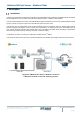
IntesisTM BACnet Server – Modbus Client User Manual r1.9 eng 1 Description Introduction This document describes the integration of Modbus RTU and Modbus TCP installations into BACnet MSTP or BACnet IP compatible devices and systems using the Intesis BACnet Server – Modbus Client gateway. The aim of this integration is to make accessible Modbus system signals and resources from a BACnet based control system or device, as if it was a part of the own BACnet system and vice-versa.
IntesisTM BACnet Server – Modbus Client User Manual r1.9 eng Integration of Modbus RTU Slaves or Modbus TCP Servers to BACnet IP control and monitoring systems © HMS Industrial Networks S.L.U - All rights reserved This information is subject to change without notice URL https://www.intesis.
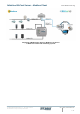
IntesisTM BACnet Server – Modbus Client User Manual r1.9 eng Functionality From the Modbus system point of view, after the start up process, Intesis reads continuously the points configured to be read in the Modbus TCP Server and/or Modbus RTU Slave devices and updates in its memory all the values received from the Modbus system. There are 2 available ports for Modbus RTU integration.
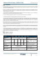
IntesisTM BACnet Server – Modbus Client User Manual r1.9 eng 2 Protocol Implementation Conformance Statement BACnet Protocol Implementation Conformance Statement (PICS) Date: 2018-05-16 Vendor Name: HMS Industrial Networks S.L.U Product Name: INBACMBM---0000 Product Model Number: INBACMBM---0000 Application Software Version: 1.0.3.0 Firmware Revision: 14.0.1.0 BACnet Protocol Revision: 14 Product Description: Modbus – BACnet MS/TP & BACnet IP Gateway Abstraction of Modbus Registers as BACnet Objects.
IntesisTM BACnet Server – Modbus Client User Manual r1.9 eng Device Address Binding: Is static device binding supported? (This is currently necessary for two-way communication with MS/TP slaves and certain other devices.) Yes No Networking Options: Router, Clause 6 - List all routing configurations, e.g., ARCNET-Ethernet, Ethernet-MS/TP, etc.
IntesisTM BACnet Server – Modbus Client User Manual r1.
IntesisTM BACnet Server – Modbus Client User Manual r1.
IntesisTM BACnet Server – Modbus Client User Manual r1.
IntesisTM BACnet Server – Modbus Client User Manual r1.
IntesisTM BACnet Server – Modbus Client User Manual r1.9 eng 5 Objects Supported Object Types The objects supported are shown in the table below.
IntesisTM BACnet Server – Modbus Client User Manual r1.9 eng Objects and properties 5.2.1 INBACMBM---0000 (Device Object Type) Property Identifier Property Datatype Value Object_Identifier BACnetObjectIdentifier Object_Name ASHRAE IBOX (Device, 246000) R R CharacterString "INBACMBM---0000" R R Object_Type BACnetObjectType DEVICE (8) (Device Object Type) R R System_Status BACnetDeviceStatus OPERATIONAL (0) R R Vendor_Name CharacterString "HMS Industrial Networks S.L.
IntesisTM BACnet Server – Modbus Client User Manual r1.
IntesisTM BACnet Server – Modbus Client User Manual r1.9 eng 5.2.
IntesisTM BACnet Server – Modbus Client User Manual r1.9 eng 5.2.
IntesisTM BACnet Server – Modbus Client User Manual r1.9 eng 5.2.
IntesisTM BACnet Server – Modbus Client User Manual r1.9 eng 5.2.
IntesisTM BACnet Server – Modbus Client User Manual r1.9 eng 5.2.
IntesisTM BACnet Server – Modbus Client User Manual r1.9 eng 5.2.
IntesisTM BACnet Server – Modbus Client User Manual r1.9 eng 5.2.
IntesisTM BACnet Server – Modbus Client User Manual r1.9 eng 5.2.
IntesisTM BACnet Server – Modbus Client User Manual r1.9 eng 5.2.
IntesisTM BACnet Server – Modbus Client User Manual r1.9 eng 5.2.
IntesisTM BACnet Server – Modbus Client User Manual r1.9 eng 5.2.
IntesisTM BACnet Server – Modbus Client User Manual r1.9 eng 5.2.
IntesisTM BACnet Server – Modbus Client User Manual r1.9 eng 5.2.
IntesisTM BACnet Server – Modbus Client User Manual r1.9 eng 5.2.
IntesisTM BACnet Server – Modbus Client User Manual r1.9 eng 6 Connections Find below information regarding the Intesis connections available. Power Supply Must use NEC Class 2 or Limited Power Source (LPS) and SELV rated power supply. If using DC power supply: Respect polarity applied of terminals (+) and (-). Be sure the voltage applied is within the range admitted (check table below). The power supply can be connected to earth but only through the negative terminal, never through the positive terminal.
IntesisTM BACnet Server – Modbus Client User Manual r1.9 eng Powering the device A power supply working with any of the voltage range allowed is needed (check section 9). Once connected the RUN led (Figure above) will turn on. WARNING! In order to avoid earth loops that can damage the gateway and/or any other equipment connected to it, we strongly recommend: • • The use of DC power supplies, floating or with the negative terminal connected to earth.
IntesisTM BACnet Server – Modbus Client User Manual r1.9 eng Connection to Modbus 6.3.1 Modbus TCP Connect the communication cable coming from the network hub or switch to the ETH port of Intesis. The cable to be used shall be a straight Ethernet UTP/FTP CAT5 cable. 6.3.2 Modbus RTU Connect the communication cable coming from the Modbus network to the port/s marked as Modbus of Intesis. Connect the EIA485 bus to connectors A3 (A-), A4 (B+) and A1 or A2 (SNGD) of gateway’s PortA. Respect the polarity.
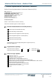
IntesisTM BACnet Server – Modbus Client User Manual r1.9 eng 7 Status LEDs and push buttons LED Run Error Port A (Tx/Rx) – Modbus RTU Colour Off Green Off Red Off Tx - Blinking green Rx – Blinking yellow Port B (Tx/Rx) – Modbus RTU (Using BACnet/IP protocol) Off Tx - Blinking green Rx – Blinking yellow Port B (Tx/Rx) – BACnet (Using BACnet/MSTP protocol) Off Tx - Blinking green Rx – Blinking yellow Indication No power Device powered and working. No error Error There is no activity on this port.
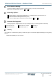
IntesisTM BACnet Server – Modbus Client User Manual r1.9 eng 8 Set-up process and troubleshooting Pre-requisites It is necessary to have a BACnet IP client or MSTP device operative and well connected to the corresponding BACnet port of Intesis and a Modbus RTU slave or Modbus TCP client connected to their corresponding ports as well. Connectors, connection cables, PC to use the configuration tool and other auxiliary material, if needed, are not supplied by HMS Industrial Networks S.L.
IntesisTM BACnet Server – Modbus Client User Manual r1.9 eng Figure 8.1 MAPS connection © HMS Industrial Networks S.L.U - All rights reserved This information is subject to change without notice URL https://www.intesis.
IntesisTM BACnet Server – Modbus Client User Manual r1.9 eng 7.2.3 Configuration tab Select the Configuration tab to configure the connection parameters. Three subsets of information are shown in this window: General (Gateway general parameters), BACnet Server (BACnet interface configuration) and Modbus Master (Modbus interface parameters). Figure 8.2 Intesis MAPS configuration tab 7.2.
IntesisTM BACnet Server – Modbus Client User Manual r1.9 eng Figure 8.3 Intesis MAPS Signals tab 7.2.5 Sending the configuration to Intesis When the configuration is finished, follow the next steps. 1.- Click on Save button to save the project to the project folder on your hard disk (more information in Intesis MAPS User Manual). 2.- You will be prompted to generate the configuration file to be sent to the gateway. a.
IntesisTM BACnet Server – Modbus Client User Manual r1.9 eng Figure 8.4 Intesis MAPS Receive/Send tab After any configuration change, do not forget to send the configuration file to the Intesis using button Send File. 7.2.6 Diagnostic To help integrators in the commissioning tasks and troubleshooting, the Configuration Tool offers some specific tools and viewers. In order to start using the diagnostic tools, connection with the Gateway is required.
IntesisTM BACnet Server – Modbus Client User Manual r1.9 eng Figure 8.5 Diagnostic More information about the Diagnostic section can be found in the Configuraion Tool manual. © HMS Industrial Networks S.L.U - All rights reserved This information is subject to change without notice URL https://www.intesis.
IntesisTM BACnet Server – Modbus Client User Manual r1.9 eng Set-up procedure 1. Install Intesis MAPS on your laptop, use the setup program supplied for this and follow the instructions given by the Installation wizard. 2. Install Intesis in the desired installation site. Installation can be on DIN rail or on a stable not vibrating surface (DIN rail mounted inside a metallic industrial cabinet connected to ground is recommended). 3.
IntesisTM BACnet Server – Modbus Client User Manual r1.9 eng 9 Electrical & Mechanical Features Enclosure Mounting Terminal Wiring (for power supply and low-voltage signals) Power Ethernet Port A Plastic, type PC (UL 94 V-0) Net dimensions (dxwxh): 90x88x56 mm Recommended space for installation (dxwxh): 130x100x100mm Color: Light Grey. RAL 7035 Wall. DIN rail EN60715 TH35. Per terminal: solid wires or stranded wires (twisted or with ferrule) 1 core: 0.5mm2… 2.5mm2 2 cores: 0.5mm2… 1.
IntesisTM BACnet Server – Modbus Client User Manual r1.9 eng 10 Dimensions 56 mm (h) 88 mm (w) 90 mm (d) Recommended available space for its installation into a cabinet (wall or DIN rail mounting), with space enough for external connections 100 mm (h) 100 mm (w) © HMS Industrial Networks S.L.U - All rights reserved This information is subject to change without notice 130 mm (d) URL https://www.intesis.