
Instructions


Intesis
TM
INMBSDAI001I000
User’s Manual r2.3 EN
© HMS Industrial Networks S.L.U - All rights reserved
This information is subject to change without notice
URL https://www.intesis.com
6 / 22
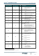
2. Connection
The interface comes with a specific cable and connectors to establish direct connection to the
AC indoor unit. It comes as well with a plug-in terminal block of 2 poles to establish direct
connection with the Modbus RTU EIA-485 network.
2.1 Connect to the AC indoor unit
To connect the INMBSDAI001I000 interface with the AC indoor unit you must follow these
steps:
Disconnect Mains Power from the AC unit. Open the front cover of the indoor unit to have
access to the electronic circuit. Once you arrive at the electronic circuit, locate the socket
connector marked as S21.
Take the cable that comes with the interface, insert one of its connectors (the one installed in
the shortest uncovered part) into the socket of the INMBSDAI001I000, and the other
connector (the one installed in the largest uncovered part) to the socket S21 of the AC unit's
electronic circuit. Remember that the INMBSDAI001I000 must also be connected to the
Modbus RTU EIA-485 network. Close the AC indoor unit's front cover again to finish the
connection.
Do not modify the length of the cable supplied with the interface, it may affect the correct
interface´s operation.
2.2 Connection to the EIA-485 bus
Connect the EIA-485 bus wires to the plug-in terminal block (the one of two poles) of
INMBSDAI001I000 and keep the polarity on this connection (A+ and B-). Make sure that the
maximum distance to the bus is 1,200 meters (3,937 ft). The loop or star typologies are not
allowed in the case of the EIA-485. A terminator resistor of 120Ω must be present at each
end of the bus to avoid signal reflections. The bus needs a fail-safe biasing mechanism (see
section 4.6 for more details).
S21
AC indoor unit
Electronic circuit board
200 mm / 7.9”
40 mm / 1.6”
Connection cable
supplied within the
interface.
90 mm / 3.5”
Modbus RTU
EIA-485
Bus
EIA485
A B
AC Unit
53 mm / 2.1”
Use these holes to
attach the cable
using the staple and
screw provided with
the interface.
For wall mounting,
extract the upper and
lower staples until
you listen the "click".
Fixing screw