
Instructions


Intesis
TM
INMBSDAI001I000
User’s Manual r2.3 EN
© HMS Industrial Networks S.L.U - All rights reserved
This information is subject to change without notice
URL https://www.intesis.com
8 / 22
4. Modbus Interface Specification
4.1 Modbus physical layer
INMBSDAI001I000 implements a Modbus RTU (Slave) interface, to be connected to an EIA-
485 line. It performs an 8N2 communication (8 data bits, no parity and 2 stop bit) with
several available baud rates (2400 bps, 4800 bps, 9600 bps -default-, 19200 bps, 38400
bps, 57600 bps, 76800 bps and 115200 bps). It also supports 8N1 communication (8 data
bits, no parity and 1 stop bit).
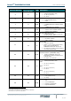
4.2 Modbus Registers
All registers are type “16-bit unsigned Holding Register” and they use the standard ModBus
big endian notation.
4.2.1 Control and status registers
Register Address
(protocol address)
Register Address
(PLC address)
R/W
Description
0
1
R/W
AC unit On/Off
▪ 0: Off
▪ 1: On
1
2
R/W
AC unit Mode
1
▪ 0: Auto
▪ 1: Heat
▪ 2: Dry
▪ 3: Fan
▪ 4: Cool
2
3
R/W
AC unit Fan Speed
1
▪ 0: Auto
▪ 1: Low
▪ 2: Mid-1
▪ 3: Mid-2
▪ 4: Mid-3
▪ 5: High
3
4
R/W
AC unit Up/Down Vane Position
1
▪ 0: Off (Default)
▪ 10: Swing
4
5
R/W
AC unit Temperature setpoint
1,2,3
▪ -32678 (Initialization value)
COOL
▪ 18..32 ºC (ºC/x10ºC)
▪ 64..92 ºF
HEAT
▪ 16..30 ºC (ºC/x10ºC)
▪ 61..88 ºF
AUTO
▪ 18..30 ºC (ºC/x10ºC)
▪ 64..88 ºF
1
Available values will depend on the AC unit mode. Check the AC unit model functions in its user manual to know the possible
values for this register.
2
Magnitude for this register can be adjusted to Celsius x 1ºC, Celsius x 10ºC (default) or Fahrenheit. See section 4.2.3 for more
information
3
It is not possible turn to x10 the value shown in Fahrenheit.