
Installation Guide
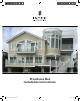

RS70 Providence Rail System Installation Instructions
RS70INST-1 (05/06/2019)
Level Rail Section Application (NOTE: for 3-Line Rail, read Section 5 first before starting at
Section 1)
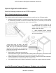
1. Measure to determine baluster layout, cut rail sections to length.
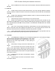
a. Ensure newels or columns to which rail will be mounted are plumb and sturdy enough to
support rail. If newel/column covers are used, ensure they have blocking at each location where
railing will be attached.
b. Measure span at top and bottom rail locations.
c. For standard baluster spacing (with the variable spaces at the ends of each rail section),
a re-useable template/jig kit is available separately (Item # RS70BALJIG). Alternately the pre-
marked locations inside the top/bottom common rail can be used. Hold one section of the Top/Bottom
Common Rail at the bottom of the newels, and using the pre-marked locations as a reference,
determine the best end baluster spacing by either locating a baluster directly at the center of the rail
section, or the mid-point between two balusters as the center of the rail section. Once the best end
baluster spacing is decided, mark both ends of the rail at the newels and square cut using a miter
box. The Top and Bottom Common Rail must be cut with exactly the same spacing, to ensure that
the balusters will be plumb. Cut the Rail Top Cap to the required length.
d. If equal spacing between all balusters and the newels/columns is desired, disregard
section ‘c’ above and determine spacing based upon width and number of balusters (Note: check
local building codes for maximum spacing allowed).
2. Drill and assemble rail/baluster section.
a. Using the decided upon spacing, at the center of the location for each Baluster, drill a 1/8”
hole through the Top and Bottom Common Rail at the centerline.
b. Secure each Baluster with one baluster screw 🅒 through the Top Common Rail, and one
through the Bottom Common Rail. Ensure Balusters are straight and aligned and secure with one
baluster lock screw 🅓 through the Bottom Common Rail (offset from center) to preclude Baluster
from rotating after installation.
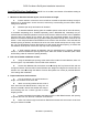
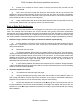
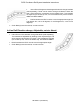
3. Prepare aluminum reinforcements.
a. Cut the aluminum rail reinforcements to
length, 1/4” shorter than the PVC rails.
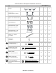
b. Attach a mounting bracket to both ends of
each Aluminum Rail Reinforcement, using four rail
bracket screw 🅐. Lubricate the threads with soap to
avoid binding and use a clutch type drill to avoid
stripping screws.
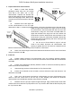
c. Locate crush block(s) provided to the bottom Aluminum Rail Reinforcement, with spacing
no greater than 36” from the end, or between Crush Blocks.
d. Drill a 3/16” hole through the Aluminum Rail Reinforcement and secure each crush block
using one baluster screw 🅒.