
Installation Guide
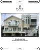

RS70 Providence Rail System Installation Instructions
RS70INST-1 (05/06/2019)
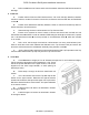
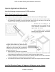
e. Drill one additional 3/16” hole at each end of the bottom Aluminum Rail Reinforcement for
drainage.
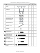
4. Install rail
a. Position bottom Aluminum Rail Reinforcement, with crush block(s) attached, between
newels or columns, centered in newel or column face, and secure each end with two rail attachment
screws 🅑.
b. Position PVC rail/baluster assembly between newels or columns and seat fully down on
bottom aluminum rail reinforcement.
c. Seat remaining aluminum reinforcement into Top Common Rail.
d. Ensure rail is centered on face of newel or column and secure each end with two rail
attachment screws 🅑. NOTE: in order to maintain CCRR rating for rail lengths in excess of 8’, replace
the 3” rail attachment screws 🅑 on the top rail with 4” rail attachment screw 🅔, which are included
in 10’ rail kits.
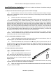
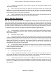
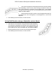
e. Drill a 3/16” hole through the aluminum reinforcement over every third baluster (note:
offset to avoid the screw which attaches the Baluster to the Top Common Rail) and secure the
aluminum reinforcement to the rail/baluster assembly using baluster screws 🅒
f. Apply a bead of latex caulk at the contact areas where the Rail Top Cap seats on the Top
Common Rail. Seat the Rail Top Cap fully onto the Top Common Rail.
5. 3-Line Rail
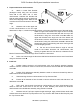
a. Cut all Balusters to height (24” for 36” finished rail height, 30” for 42” finished rail height).
Cut the remaining short pieces of the balusters to 3-7/8”. These
will be the spacer balusters for the upper section, and can be
aligned one over each longer baluster, or other spacing as
desired (36” max).
b. Follow steps 1 through 4e above to install lower rail
section.
c. 3-Line rail sections use the ‘flat’ Top Rail Cap as the
bottom for the upper section. Determine the spacer baluster
locations and mark this flat cap and the upper rail Top Common
Rail at the desired locations. Secure the 3-7/8” spacer balusters
as in section 2 above.
d. Install the lower rail section as described in Section
4b through 4f above.
e. Install the upper rail section as described in Section
4b through 4f above.