
Installation Guide

RS70 Providence Rail System Installation Instructions
RS70INST-1 (05/06/2019)
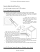
f. Ensure rail is centered on face of newel or column and secure each end with two rail
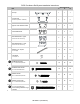
attachment screws 🅑.
g. Drill a 3/16” hole down through the aluminum reinforcement and the Top Common Rail
between the first and second baluster at both ends and near the center of the span (all between
balusters). Countersink holes from underside of the Top Common Rail for a #8 Screw to ensure that
screw seats flush with PVC and to prevent stripping.
h. Apply a bead of latex caulk at the contact areas where the Rail Top Cap seats on the Top
Common Rail. Seat the Rail Top Cap fully onto the Top Common Rail.
Stair or Rake Rail Application
Note: IBC code requires that finished stair rail heights be a minimum of 34" plumb off the nose of the
tread. The standard RS70 Providence 36" rail kit’s balusters will typically meet these requirements
provided the rail is being installed with the bottom rail elevated above the stair treads. In the event that
the railing is being installed directly at or slightly above the stair tread nose, INTEX recommends using
the RS70 Providence Stair/Rake Rail kit, which will meet the minimum height requirement any scenario.
1. Determine angle, measure rail lengths and determine baluster layout/spacing
a. Ensure newels or columns to which rail will be mounted are plumb and sturdy enough to
support rail. If newel/column covers are used, ensure they have blocking at each location where
railing will be attached.
b. Determine and mark angle.
c. For standard baluster spacing (with the variable spaces at the ends of each rail section),
use the pre-marked locations inside the Top and Bottom Common Rail. Determine best end spacing
by either locating a baluster directly at the center of the rail section, or the mid-point between two
balusters as the center of the rail section. Once Baluster spacing is determined, cut end(s) of Top
and Bottom Common Rail to angle and length. Note: do not cut Rail Top Cap until section is
assembled and secured at all 4 mounting points.
d. If equal spacing between all balusters and newels/columns is desired, disregard Section
c above and determine spacing based upon width and number of balusters (Note: check local building
codes for maximum spacing allowed).
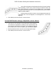
2. Assemble rail/baluster section.
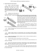
a. Trim Balusters to required length and angle.
b. Using the decided upon spacing, at the center of the location for each Baluster, drill a 1/8”
hole through the Bottom Common Rail at the centerline, at the angle of the Baluster attachment.
Repeat this for process for the Top Common Rail, using the same spacing.
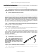
c. Secure each baluster with one baluster screw 🅒 through the Top Common Rail, and one
through the Bottom Common Rail. Ensure balusters are straight and aligned and secure with one
baluster lock screw 🅓 through the bottom rail (offset from center) to prevent the baluster from rotating
after installation.