
User Manual


254
PO
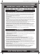
S AVE THESE INSTRUCTIONS
(254PO) SPA ENGLISH 7.5” X 10.3” PANTONE 295U 05/29/2015
English
SET UP
(continued)
Setup the spa with at least 2 persons.
1.
Move the entire package to the selected site. Do not drag the spa tub across the ground as this can
cause damage and leakage.
Open the carton carefully as this carton can be used to store the spa during long term storage or when
not in use.
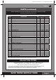
2.
Lay out all the parts on the ground and make sure all the parts are accounted for
.
For missing or
damaged parts contact the appropriate Intex Service Center listed in the separate “Authorized service
Centers” sheet.
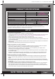
Safety Sign Card Posting
The Safety Sign card included with the manual shall be posted in an area visible to the users of the spa to
alert them of the safety rules and warnings. For replacement of the safety sign card, visit our website at
www.intexcorp.com for additional print copies. Laminate the printed safety sign copy for protection from the
elements.
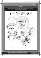
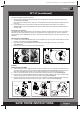
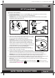
Spa Control Unit Assembly
1.
Connect the control panel
(3)
cable plug into the receptacle on top of the spa control base and screw in
the plug cover rmly by hand
(see drawing 1).
2.
Screw the control panel bolts
(4)
with the provided bolt wrench
(6)
to secure the control panel
(see drawing 2).
3.
Plug the spa control unit into a grounded electrical outlet.
Page 8
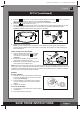
Ination
Inate the Spa Tub Wall
1.
Take out the ground cloth
(19)
and spread it over the cleared area. Then spread out the spa liner over
the ground cloth and point the drain valve towards a suitable draining area.
Note:
Spread the ground
cloth with the bubbles facing down over the cleared area where you intend to setup your spa.
2.
Press the button located on top of the control base
and remove the back cover
(see drawing 3).
3.
Unscrew the control base ination cap
(5)
to reveal the air blower ination outlet, insert one end of the
ination hose
(7)
into the outlet and turn to the right to lock it
(see drawing 4).
4.
Unscrew the air valve cap to reveal the stem in the up position for ination. Insert the other end of the
ination hose
(7)
into the valve and turn to the right to lock it in position
(see drawing 5)
.
4
6
2
1
3
1
2
3
Press
4
5
5
7
7
1 2