
Operation Manual


264
PO
S AVE THESE INSTRUCTIONS
(264PO) SPA (JET + BUBBLE) ENGLISH 7.5” X 10.3” PANTONE 295U 10/19/2016
English
Page 9
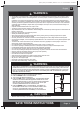
SET UP (continued)
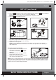
6.
Disconnect the infl ation hose
(7)
from the air valve and attach the pressure gauge
(5)
to the air valve.
The pressure gauge indicator should be in the green area for a properly infl ated spa tub
(see drawing 6)
.
Repeat previous steps to add more air if necessary.
7.
Replace the air valve cap back.
NOTE:
The cap is designed to be screwed on and off. Never exert force as this could cause the
complete internal infl ation system of the valve to come loose. See “Spa Tub Air Valve Fastening” for
valve maintenance.
Infl ate the Spa Cover Air Bladder
1.
Open the infl ation valve and insert the infl ation
hose
(7)
into the valve; press to infl ate
until it is fi rm to the touch but not hard
(see
drawing 7)
.
2.
Disconnect the infl ation hose
(7)
from the air
blower infl ation outlet and the valve.
3.
Replace the control base infl ation cap
(9)
back;
close and recess the infl ation valve.
NOTE:
If there is a need to add some air to the spa tub wall or spa cover air bladder after they have been
setup, refer to above “Infl ate the Spa Tub Wall” and “Infl ate the Spa Cover Air Bladder” sections. The cover
air bladder is preinstalled inside the spa cover. If it needs to be reinstalled, place the uninfl ated air bladder
inside the spa cover lip before infl ating the bladder.
5
4
7
1 2
7
7
6
5
1
2
3
9
24
4.
Press the button to turn on the control unit panel buttons fi rst. Press the button to infl ate the
spa tub wall until it is fi rm to the touch but not hard
(see drawing 5)
.
IMPORTANT:
Do not over infl ate or use high pressure air compressor to infl ate.
5.
Press the button again to turn it off.