
Instruction Manual

241
PO
(241PO) SALTWATER SYSTEM & SAND FILTER PUMP (14” & 16”) ENGLISH 7.5” X 10.3” PANTONE 295U 07/18/2013
English
SAVE THESE INSTRUCTIONS
Page 11
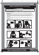
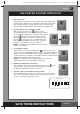
6-way valve installation:
1. Lower the 6-way valve over the tank slowly, and ensure the bypass pipe protruding
underneath the 6-way valve fits securely into the center pipe hub (8) top opening (see
drawing 19).
IMPORTANT: There are three hose connection ports on the 6-way valve, ensure the
outlet connection (from filter to the pool) on the valve is facing towards the pool, and
the inlet connection (from motor to valve) is aligned with the motor outlet (see
drawing 20).
2. Remove the clamp bolt, and install the clamp around the tank and 6-way valve flanges, then
replace the clamp bolt and use a phillips screwdriver (not included) to tighten it. (see
drawing 21).
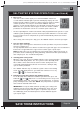
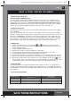
SETUP INSTRUCTIONS (continued)
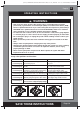
WARNING
Improper tank valve and clamp assembly could cause the valve and clamp to blow off
and cause serious injury, property damage or death.
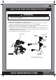
3. Connect the sand filter interconnecting hose (13) between the 6-way valve inlet and motor
outlet, and insert the electrolytic cell (22) into the 6-way valve outlet. Hand tighten them
securely (see drawings 22 and 23).
22
23
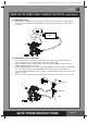
4. Screw and tighten the flow sensor (21) to the electrolytic cell (22), then plug in the
electrolytic cell line cord and tighten the nut (see drawings 24 and 25).
24
25
13
21
22
22
6
19
20
WATER
INLET
WATER
OUTLET
21
8