
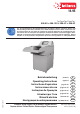
Product Manual
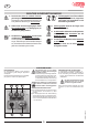

INSTALLATION REQUIREMENTS:
Be certain that three phase current is available at
the point of installation (see TECHNICAL DATA
for information concerning required pre-fusing of
the electrical outlet).
Note: Since this machine can weigh up to 475
kg, it is essential to check the permissible load
per square meter of the oor.
intended purpose!
in closed rooms within a temperature
range of 10 to 40° C!
SUMMARY OF NUMBERED PARTS:
6 = Housing (g. 1, 2, 4)
7 = Table (g. 1, 2, 4, 5, 6)
8 = Guard panel (g. 1, 2, 4)
9 = Bag frame (g. 9)
10 = Discharge door (g. 9)
11 = Rubber band (g. 9)
12 = Conveyer belt (g. 1, 2)
13 = Conveyor belt retainer (g. 1)
14 = Cable holders (g. 6)
15 = Angle guard (g. 5) (optional)
SETTING UP THE SHREDDER:
1. Remove the external wooden covers.
2. Remove the protective sheet material.
3. Lift the machine little by little from the pallet with
the help of a pallet jack, and then set it onto the
oor on the rollers.
Note: The pallet must be unscrewed and
dismantled piece by piece to this end, and the
machine must be grasped, lifted and set back
down again with the pallet jack after each dis-
mantling operation.
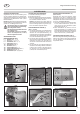
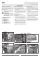
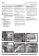
POSITIONING OF THE TABLE (7)
(gs. 1, 2 and 3):
1. Unscrew each of the 3 screws with washers
on the front wall of the housing (6) and on the
front of the conveyor belt attachment (13) as
well as the one screw on both sides under the
protective plate (8) (see arrow markings g.
1).
2. Slightly undo each of the upper screws on the
left and right of the protective plate (see arrow
marking g. 2), swivel the table (7) forwards
through 180° and tighten both screws again.
3. Using the previously unscrewed eight screws
and washers, screw the table to the housing
(3 at the front, 2 on the side) and the front
of the conveyor belt attachment (3 screws)
(g. 3).
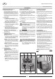
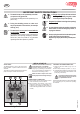
INSTALLATION OF THE
PROTECTIVE BRACKET (15) (gs. 4 and 5):
If required, the contact surface of the table
can be widened by installing two protective
brackets (15) (g. 5) instead of the two protective
plates (8) (g. 4) (see also under “SPECIAL
ACCESSORIES”)
1. Unscrew each of the 4 screws with washers
on the side wall of the housing (6) on the left
and right and on the table (see arrow markings
g. 4).
2. Remove both protective plates (8) and screw
the two protective brackets (15) onto the side
wall of the housing (6) on the left and right and
to the table (7) with the aid of the previously
unscrewed screws and washers.
COILING UP THE POWER CABLE (g. 6):
If the entire length of the power cable is not required
at the respective location, or when moving the ma-
chine from one location to another, the power cable
can be coiled up around the cable holders.
g. 3
g. 2
g. 1
g. 4 g. 6
g. 5
13
12
7
8
6
7
8
12
8
7 15
14
14
6
7
7
6
86434 12 08/16
6
INSTALLATION
Translation of the Original Operation Manual
Übersetzung der Originalbetriebsanleitung
GB