Quick installation guide V1.0 May 2015 Intracom Asia Co., Ltd.
This guide describes how to quickly install CPE and how to easily configure outdoor CPE step by step followed the guidance which offers a very visual way to help end user/ maintenance staff of network etc spent a little bit time to have a whole ideas how to make CPE work fine.
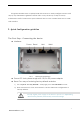
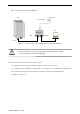
Connection means as figure-2: 120V AC CPE Power Adapter PC POE Mixer POE LAN LAN Figure-2 Caution CPE connect to POE Mixer & Power adapter diagram Incorrect connection means or plug in power supply which don’t belong to the package may cause device damage! The Second Step: Start-up and Login 1)As figure-2 shown, please make it ready for CPE connect with PC 2)Consign local IP address with 192.168.2.
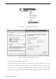
Figure-3 Configure IP address of PC Figure 4 LAN IP address settings on PC side 3)Connecting to equipment via wireless After basic settings of the equipment, if you want to access internet or just the equipment via wireless, please configure local” Wireless Network” properties, lock mouse on the icon of Wireless Network then click right button of mouse, you’ll see figure- 5 shown, then click “View Available Wireless Network” to filter out which AP or 3 Intracom Asia Co., Ltd.
router you wish to connect with. Defaults SSID:CPE-XXXX; Defaults Password: blank Figure- 5 Wireless Network Icon Figure- 6 Wireless Connection Settings 4 Intracom Asia Co., Ltd.
A. If your Laptop or PC has internal wireless 802.11b/g/n LAN card, but couldn’t find wireless network, please contact with service department of your computer vendor for help: Caution 1) Click right button upon “My Network Places”, then select “Properties”, if you could find “Local Network” but there is no “Wireless Network” icon.
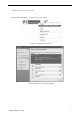
Enter encryption password→Select specified WAN type PPPOE、DHCP、Static →click Next Step Figure – 9 WISP Settings Note: DHCP : If the device connect to DHCP Server of uplink or WISP,pls select this mode.The device will obtain IP address from uplink DHCP server or WISP automatically. PPPoE: If WISP offer PPPOE access type,pls select this mode.
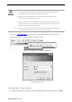
Figure - 11 DHCP Server Settings ④Wireless Settings: To configure wireless settings of the device,you could enable or disable wireless here,select security mode/set encrypt key etc,after that click Apply to save previous settings. Figure - 12 Wireless Settings Note: The device will reboot after changing these settings, if you just keep defaults value pls click Next for further process 7 Intracom Asia Co., Ltd.
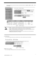
The Fourth Step: AP Client Settings AP Client:In this mode,the device associate with nearby AP and checks the network device combination as a standard mobile unit(MU).The access point then forms a wireless bridge between the wired LAN and clients through the device. CPE broadcasting its SSID, client devices obtain IP address from uplink hotspot or WISP. Note: Both Ethernet port are LAN port on AP Client、AP、WISP mode.
Figure - 14 Note: Note: AP Client settings Channel without setting, since Channel of the CPE will automatically consistent with the front end WLAN base station in AP and AP Client mode. CPE will disable its DHCP server in AP Client mode, for management purpose you can assign different IP address for each CPE If there is no targeted SSID in checking list, you’d better have some more “Scan” process.
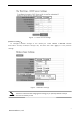
Figure -16 WDS Settings WDS Bridge/Repeater setup just same with AP Client mode generally.but front end AP support WDS is a must when CPE is in WDS mode. Note: The fourth step: AP settings Go to check “Operation Mode”→“Access Point(AP)”,you’ll see figure -17 page. In this page you may set wireless access point related options by your needing,after that please click ”Apply” to save settings and reboot device. 10 Intracom Asia Co., Ltd.
Figure - 17 AP Settings Select specified one you wish to enable its SSID, click”Enable”. Once you enable BSSID, you could select one Channel and configure specified wireless parameter based the BSSID, also you could enable multiple SSID option. Once enable SSID CPE will broadcast its name. Select SSID blank you can change its name here.
The Fifth step: Router(Gateway) Configuration Click”Operation Mode”→“Router(Gateway)” go to basic configuration page,as figure -12 shown: Note: Router(Gateway) is what we usually say SOHO router function,Router connect to wired ISP to access internet(usually be ADSL,Cable etc). Here no detailed description, if necessary, please refer to typical SoHo wireless router configuration. Figure - 12 DHCP: When the Device connects to a DHCP server, or ISP support DHCP service, please choose this type.
Figure - 19 CPE Connection Status When CPE successfully connect with front-end WLAN base station or AP, the status will be “Connected”, also other options listed on the page .e.g “Peer-end SSID”,MAC address, RSSI etc Note: Signal strength should be greater than ‐75dBm,if it’s weak than this CPE’s Bridge/Repeater joint will be worse.
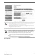
Figure - 20 IP address settings on PC Once you finished this setting, you can implement “Ping” command to test if the connection is done. 3 System Click “System” to go to system management page, as shown in Figure – 21. Figure - 21 System Management Password Settings: To set system administrator and password here. Time Settings: To set time zone and time information here.
Factory Defaults: Restore system configuration to factory defaults. Reboot: re-power on system by software interface. WEB Server: To set web server related option here. Firmware Upgrade: To upgrade CPE’s firmware for obtaining a more stable and functional performance of the CPE. Note: To restore CPE to factory defaults via physical reset button on housing by pressing reset button in 5‐10s or click “Reset” button on web page.
4 Troubleshooting: Troubles SYS indicator doesn’t shine Couldn’t login Web page CPE could not connect with front-end AP ( Status: disconnected) Couldn’t detect targeted CPE signal of Treatment Please double check if the connection is done between POE box and LAN port. Right way is that put “POE” interface connect with CPE and “LAN” with PC or laptop. 1. Please check if both IP address is in same range. You can check it via selecting “Start”-“Run” bland and implementing “CMD” command, by ping “192.168.
*. This device complies with Part 15 of the FCC Rules. Operation is subject to the following two conditions: (1) This device may not cause harmful interference, and (2) This device must accept any interference received, including interference that may cause undesired operation. Changes or modifications not expressly approved by the party responsible for compliance could void the user's authority to operate the equipment. 17 Intracom Asia Co., Ltd.