
Installation Manual
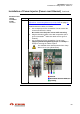
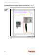
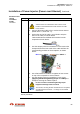
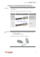
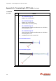
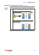
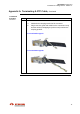
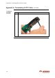
Table Of Contents
- Revisions
- Reasons of change
- Introduction
- Regulations
- General installation guidelines
- (RF exposure)
- Compliance boundary definition
- Table of Contents
- 1. Introduction
- Scope of document
- Target Audience
- Reference manuals
- Conventions
- 2. Prior to Installation
- Topics
- Packing list materials
- Powering materials
- Power injectors
- Power cables
- Power modules & connectors
- Grounding materials
- Data traffic materials
- S-FTP cables
- Fiber optic cables
- SFP
- Pole fastening materials
- Mounting bracket
- Steel hose clamps
- Cable ties
- StreetNodeTM 6250 PTP(1)
- Outdoor DC PonE
- Outdoor AC PonE
- Indoor AC PoE
- Anchor point
- / /
- Introduction
- Site survey
- Preparation of the installation premises
- Network port distributors
- Cables routing (lamp post)
- Power cable routing
- Cable conduits
- Wall installation
- Installation location
- Lamp post or pole
- Grounding
- Outdoor grounding system
- Power supply source
- Circuit breakers
- Line Of Sight (LOS) verification
- Lightning & Surge protection
- Internal ovp(2)
- Safety
- Introduction
- Cable length restrictions
- Instruction
- Topics
- Equipment installation tools
- Ethernet cable termination tools
- Power supply cable termination tools
- Grounding cable termination tools
- 3. Installation of StreetNode 6250 PTP
- Mechanical Installation & Grounding
- Installation of Traffic Cable(s)
- Installation of Power Cable (Direct Powering)
- Installation of Power Injector (Power over Ethernet)
- Appendix A: Terminating Ethernet (S-FTP) Cable
- Appendix B: Terminating Power Supply Cable
- Appendix C: Terminating Grounding cable
- Appendix D: Removing StreetNode 6250 PTP
- Appendix E: Standards of Compliance
- Precautions
- Topics
- Tools and materials
- Lamp post (or pole) installation procedure
- Grounding cable installation procedure
- Topics
- Tools and materials
- Ethernet (S-FTP) cable installation procedure
- Ethernet (S-FTP) cable installation with SFP
- Ethernet (S-FTP) cable installation with SFP
- Topics
- Tools and materials
- Procedure
- Introduction
- Topics
- Tools and materials
- Mechanical and cabling installation (PonE)
- Cabling installation (PoE)
- Introduction
- Parts of RG-45 jack
- Termination procedure
- Procedure
- Topics
- Procedure

StreetNode™ 6250 PTP
Installation & Cabling Manual - Edition 2.1
65
Installation of Power Injector (Power over Ethernet), Continued
Mechanical and
cabling
installation
(PonE),
continued
Step Action
4 Install the power supply cable, as follows:
Switch-off the Local DC Power Source & the circuit
breaker connected between PonE and the Local DC
Power Source.
a. Connect the power cable to the Local DC Power Source
(Brown wire: +V, blue wire: -V).
b. At the other end of the cable, use a blade to strip the
wires of the cable, as shown below.
Twist strands well to facilitate their insertion into the
receptacle of PonE device.
c. Use the tamper-proof torx screwdriver T10 to remove the
clamp and insert the bare ends of the cable well into the
corresponding positions of the receptacle, as shown
below:
Blue wire to INPUT -, Brown wire to INPUT +.
d. Use a flat-headed screwdriver to tighten the two screws
on top of the receptacle to secure strands.
e. Use the tamper-proof torx screwdriver T10 to screw
(applying maximum tightening torque of 0.9 Nm) the
clamp for securing the cables in place.
Do not exceed the maximum tightening torque.
Equipment damage will be occurred.
The screws, securing the wire strands into the receptacle,
are well isolated each other – no danger for accidental
short circuit.
End of procedure.
Continued on next page