
User's Manual
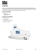
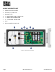


Table Of Contents
- REMOTE UNIT
- INTENTIONALLY BLANK
- Table OF CONTENTS
- CUSTOMER SUPPORT
- Bin-Sense REMOTE CERTIFICATIONS
- MANUFACTURER’S WARRANTY
- SAFETY
- OVERVIEW
- INSTALLATION
- INSTALLATION TIPS
- REMOTE UNIT INSTALLATION
- 1. Place the Remote unit on the top of the bin with the lid latches and link cables pointing towards the ground.
- 2. Place the unit where it as clear line-of-site to the Master unit external antenna and is easily accessible for future service and maintenance. The magnetic feet will hold the unit in place on the roof of the bin.
- 3. Mount the solar panel on the bin facing the direction of maximum sunlight (face south in the northern hemisphere, face north in the southern hemisphere). The solar panel has magnetic feet and can be mounted directly on the bin roof, or on a mounti...
- 4. Make sure the Remote unit solar panel connection can reach to the solar panel location.
- 5. Connect the Remote unit sensor link cable to all the sensing cables and to any other Bin-Sense accessories (e.g. Fan Controllers). You’ll need to use a terminal box or splitter to connect more than one device to the sensor link cable.
- 6. Install the three AA batteries in the Remote unit. Secure the batteries in place with the hook-and-loop strap.
- 7. Connect the Remote unit solar panel connection to the solar panel.
- 8. Refer to the Bin-Sense Live Startup Manual for further instruction on how to get the Bin-Sense Live system up and running.
- OPERATION
- INTENTIONALLY BLANK

Page 14 March 2022 Version 1.0 www.binsense.com
nothing is detected on the sensor cable interface, the LED will flash one red flash followed by a long pause, and
then six red flashes for the radio channel.
EXAMPLE:
If you have one eight-sensor temperature cable, and one eight-sensor moisture cable connected to a Master
unit that is set to radio channel 22, you would expect the following flashing pattern:
• One red flash (for total temperature & moisture cables) followed by two green flashes (for number of
cables).
• Two red flashes (for the total number of sensors) followed by one orange flash (for 10) and six green
flashes (for a total value of 16).
• Three red flashes (for the number of moisture sensors) followed by eight green flashes (for eight).
• Six red flashes (for the radio channel) followed by two orange flashes (for 20) and 2 green flashes (for a
total value of 22).