
User's Guide Gigabit Ethernet Host Adapters ITIpci 5100G/GF


LSI Logic Corporation Page 46 of 56
Appendix B
Ethernet Connector
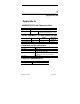
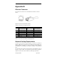
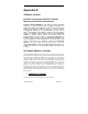
The 8-pin RJ-45 connector for 10/100/1000 Mb/sec Ethernet is wired as
shown:
Figure 9: 8-Pin RJ-45 Connector (Front)
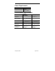
With the connection pins assigned as shown:
Contact 10Base-T Signal 100Base-TX Signal 1000Base-T Signal
1 TD+ (Transmit Data)
TD+ (Transmit
Data)
BI_DA+ (Bidi Data)
2 TD- (Transmit Data) TD- (Transmit Data) BI_DA- (Bidi Data)
3 RD+ (Receive Data) RD+ (Receive Data) BI_DB+ (Bidi Data)
4
N
ot used
N
ot used BI_DC+ (Bidi Data)
5
N
ot used
N
ot used BI_DC- (Bidi Data)
6 RD- (Receive Data) RD- (Receive Data) BI_DB- (Bidi Data)
7
N
ot Used
N
ot Used BI_DD+ (Bidi Data)
8
N
ot Used
N
ot Used BI_DD- (Bidi Data)
Table 12: 8-Pin RJ-45 Connector Pin Assignments
Network Cabling Requirements
In order for your network to operate properly, you must use a category of
network cabling that is appropriate for the data rate of the channel. For
10Mb/s operation, Category 3, or 5 cable is appropriate. When operating in
100/1000Mb/s or 100/1000Mb/s Full Duplex, a Category 5 cable should be
used.
The maximum cable segment length supported at 100/1000Mb/sec speed, on
Category 5 cable is 100M. Any single cable segment (adapter to adapter or
adapter to network hub) must be within the 100M length requirement.
87654321