ROLLITE™ROLLATORS MARCHETTES ROLLITES™ ANDADERAS RODANTES ROLLITE™ Refer to page 2. Se référer à la page 13. Refiérase a la página 28.
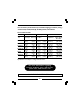
Invacare Rollators provide assistance for an individual weighing up to 300 lbs. (136 kg.) - Models 65100, 65100R, 65100-JR, 65100R-JR, 68100, and 68100-TA. ROLLITE ROLLATORS Model No.
NOTE: Check all parts for shipping damage. In case of shipping damage, DO NOT use. Contact Dealer/Carrier for further instruction. SAFETY SUMMARY To ensure the safe operation of the ROLLITE ROLLATORS, these instructions MUST be followed: GENERAL WARNING DO NOT install or use this equipment without first reading and understanding this instruction sheet.
SAFETY SUMMARY (CONTINUED) GENERAL WARNING All wheels MUST be in contact with the floor at ALL TIMES during use. This will ensure the rollator is properly balanced. The brakes MUST be in the locked position BEFORE using the seat. For optimal stability, the seat should be in the DOWN position when using the walker for ambulatory assistance. When using the rollator in a stationary position, the hand brakes MUST be locked.
SAFETY SUMMARY (CONTINUED) INSTALLATION WARNINGS Always test to see that the rollator and attachments are properly and securely locked in place BEFORE using. OPENING/FOLDING THE ROLLATOR (FIGURE 1) NOTE: Refer to the FOLDING/ASSEMBLY WARNINGS in the SAFETY SUMMARY of this manual. OPENING 1. Swing the side frames outward until the release paddles activate (engage upward). 2. Pull the handle DOWN and lower the seat.
NOTE: Back rest not shown for clarity. Model No. 65100 shown.
INSTALLING/ADJUSTING LEG EXTENSIONS/BRAKE CABLES (FIGURE 2) NOTE: Refer to the INSTALLATION WARNINGS in the SAFETY SUMMARY of this instruction sheet. NOTE: For the most comfortable position, make sure the adjustment is performed while the user is wearing the shoes he/she wears most often. NOTE: Adjust the rollator height so that when the user's arm is down to their side, the hand grip is at wrist height. This will ensure the arms are at an approximate 20° - 30° bend when using the rollator. 1.
DETAIL "A" Cable Tie Wrap Adjustment Hole Snap Button NOTE: Model No. 65100 shown.
USING/LOCKING/UNLOCKING HAND BRAKES (FIGURE 3) NOTE: Refer to INSTALLATION WARNINGS in the SAFETY SUMMARY in this instruction sheet. NOTE: If brakes prematurely lock, refer to INSTALLING/ADJUSTING LEG EXTENSIONS/BRAKE CABLES in this instruction sheet. USING HAND BRAKES 1. Pull the top portion of the brake handles UP towards the hand grips. 2. Do one (1) of the following: A. REMAIN STATIONARY - hold the brake handle UP. B. CONTINUE MOBILITY - release the brake handle. LOCKING HAND BRAKES 1.
ADJUSTING THE HAND BRAKES NOTE: COUNTERCLOCKWISE/CLOCKWISE directions are determined by standing behind the rollator (user’s position). NOTE: Refer to INSTALLATION WARNINGS in the SAFETY SUMMARY in this instruction sheet. BRAKE HANDLE (FIGURE 4) Test the brake handle. Observe how the brake lever engages the wheel. If the tension of the brake is too loose or too tight, adjust using the following steps: 1. Loosen the brake handle adjustment nut by turning CLOCKWISE. 2. Perform one (1) of the following: A.
CABLE ADJUSTER UNIT (FIGURE 5) 1. Test the brake with the brake handle. Observe how the brake lever engages the wheel. If the tension of the brake handle is STILL too loose or too tight, adjust using the following steps: Brake Lever A. Ensure brake handle is not locked. Adjustment Screw Jam Nut B. TO LOOSEN: Brace the jam nut while turning the adjustment screw CLOCKWISE. C. TO TIGHTEN: Brace the jam nut while turning the adjustment screw COUNTERCLOCKWISE. FIGURE 5 - CABLE ADJUSTER UNIT D.
LIFETIME LIMITED WARRANTY NOTE: THE WARRANTY BELOW HAS BEEN DRAFTED TO COMPLY WITH FEDERAL LAW APPLICABLE TO PRODUCTS MANUFACTURED AFTER JULY 4, 1975. This warranty is extended only to the original purchaser/user of our product. This warranty gives you specific legal rights and you may also have other legal rights which vary from state to state.
MARCHETTE ROLLITE™ Les marchettes Rollite sont conçues pour assister des personnes pesant jusqu’à 136 kg. (300 lbs.) - Models 65100, 65100R, 65100-Jr, 65100R-Jr, 68100, and 68100-TA. MARCHETTE ROLLITE Largeur Modèle No.
REMARQUE: Vérifiez que toutes les pièces sont intactes à leur arrivée. Si elles sont endommagées, N’utilisez PAS ce matériel. Prenez contact avec le distributeur ou avec le transporteur pour obtenir les instructions appropriées.
ABRÉGÉ DE SÉCURITÉ (SUITE) AVERTISSEMENT GÉNÉRAL AVANT d’utiliser le siège, les freins DOIVENT être en position serrée. Lorsque la marchette est utilisée comme aide à la locomotion, le siège doit être en position BASSE. Lorsque la marchette reste immobile, les freins DOIVENT être bloqués. Pour garantir une stabilité optimale, le siège doit être en position basse lorsque vous utilisez la marchette comme outil d’aide à la locomotion.
AVERTISSEMENTS RELATIFS À L’INSTALLATION Assurez-vous que tous les boutons de blocage sortent complètement de leurs trous de régalage sur chaque extension de pied. Ceci garantit que les extensions de pied sont solidement bloquées en position. Les extensions de pied doivent être réglées de façon à ce que la marchette soit stable.
PLIAGE 1. Levez le siège en attrapant la poignée et en la SOULEVANT. 2. Appuyez sur l’une des pédales de blocage et pivotez l’armature latérale correspondante vers l’intérieur, vers la tige transversale avant. 3. Reprenez cette procédure avec l’armature du côté opposé. REMARQUE: Appui arrière non illustré pour plus de clarté de la figure. Modèle No. 65100 (illustration).
INSTALLATION/RÉGLAGE DES EXTENSIONS DE PIED (FIGURE 2) REMARQUE: Reportez-vous aux avertissements relatifs à l’INSTALLATION qui se trouvent dans l’ABRÉGÉ DE SÉCURITÉ de ce manuel d’instructions. REMARQUE: Pour obtenir la position la plus confortable, s’assurer que le réglage soit effectué alors que l’utilisateur porte les chaussures qu’il porte le plus souvent.
REGISTER YOUR PRODUCT! The benefits of registering: 1. 2. 3. 4. 5. Safeguard your investment. Ensure long term maintenance and servicing of your purchase. Receive updates with product information, maintenance tips, and industry news. Invacare can contact you or your provider, if servicing is needed on your product. It will enable Invacare to improve product designs based on your input and needs. Register ONLINE at www.invacare.com - or Detach form, complete and mail.
1. Method of purchase: (check all that apply) ❏ Medicare ❏ Insurance ❏ Medicaid ❏ Other 2. This product was purchased for use by: (check one) ❏ Self ❏ Parent ❏ Spouse ❏ Other 3. Product was purchased for use at: ❏ Home ❏ Facility ❏ Other 4. I purchased an Invacare product because: ❏ Price ❏ Features (list features) 5. Who referred you to Invacare products? (check all that apply) ❏ Doctor ❏ Therapist ❏ Friend ❏ Relative ❏ Other ❏ No referral ❏ Advertisement (circle one): TV, Radio, Magazine, Newspaper 6.
Invacare Product Registration Form Please Seal with Tape Before Mailing 22
SCHÉMA "A" Modèle No. 65100 (illustration).
UTILISATION DES FREINS À MAIN 1. Tirez la partie supérieure des poignées de frein VERS LE HAUT, c’est à dire vers la barre d’appui. 2. Effectuez l’une (1) des opérations suivantes: A. RESTER IMMOBILE – maintenez la poignée de frein VERS LE HAUT B. POURSUIVRE LE DÉPLACEMENT – relâchez la poignée de frein. BLOCAGE DES FREINS À MAIN 1. Poussez VERS LE BAS la portion inférieure de la poignée de frein comme l’illustre la figure 3 jusqu’à ce qu’elle «clique». 2.
POIGNÉE DE FREIN (FIGURE 4) Vérifier la poignée de frein. Noter la façon dont le levier du frein s’enclenche dans la roue. Si la tension du frein est trop lâche ou trop serrée, régler le levier selon les étapes suivantes: 1. Desserrez l’écrou de réglage de la poignée de frein en le tournant DANS LE SENS DES AIGUILLES D’UNE MONTRE. 2. Effectuez l’une (1) des opérations suivantes: A. RÉDUIRE LA TENSION DE LA POIGNÉE DE FREIN – Tourner l’écrou de la poignée de frein dans LE SENS DES AIGUILLES D’UNE MONTRE.
UNITÉ DE RÉGLAGE DU CÂBLE (FIGURE 5) 1. Vérifier le frein avec la poignée de frein. Noter la façon dont le levier du frein s’enclenche dans la roue. Si la tension de la poignée du frein est ENCORE trop lâche ou trop serrée, régler le levier selon les étapes suivantes: A. S’assurer que la poignée du frein n’est pas verrouillée. B. Pour desserrer: retenir le contre-écrou tout en tournant Vis de réglage Le levier la vis de réglage dans LE SENS DES AIGUILLES D’UNE du frein Contre-écrou MONTRE. C.
5 – UNITÉ DE GE DU CÂBLE GARANTIE LIMITÉE À VIE REMARQUE : LA GARANTIE PRÉSENTÉE CI-DESSOUS A ÉTÉ MISE AU POINT EN CONFORMITÉ AVEC LA LOI FÉDÉRALE AMÉRICAINE SUR LES PRODUITS FABRIQUÉS APRÈS LE 4 JUILLET 1975. Cette garantie ne s’applique qu’à l’acheteur/utilisateur initial de notre produit. Cette garantie vous donne des droits juridiques spécifiques qui s’ajoutent aux droits applicables dans votre état.
ANDADERA RODANTE ROLLITE™ Los Andadores Invacare brindan asistencia a personas cuyo peso asciende hasta 136 kg (300 lbs).. - Models 65100, 65100R, 65100-Jr, 65100R-Jr, 68100, and 68100-TA. ANDADERA RODANTE ROLLITE Ancho Profundidad Modèle No.
NOTA: Revise todas las partes por si sufrieron daños durante el envío. Si así fuera, NO use la unidad. Comuníquese con su distribuidor/empresa de transportes para obtener mayores instrucciones. RESUMEN DE SEGURIDAD A fin de operar la ANDADERA RODANTE DE INVACARE en forma segura, es FUNDAMENTAL seguir las siguientes instrucciones: ADVERTENCIAS GENERALES Antes de instalar o usar este equipo, lea y comprenda cabalmente esta hoja de instrucciones.
ADVERTENCIAS GENERALES Trabe el freno ANTES de usar el asiento. Cuando use la andadera rodante en forma ambulatoria, el asiento debe estar en la posición de ABAJO. Para obtener una estabilidad óptima, el asiento debe estar en la posición de abajo cuando se use el rodador a fin de brindar ayuda ambulatoria. Trabe el freno de mano cuando use la andadera rodante en la posición estacionaria.
ADVERTENCIAS SOBRE LA INSTALACIÓN Ajuste las extensiones de las patas para que la andadera rodante quede nivelada. Si no se puede obtener una altura nivelada, ajuste las extensiones de las patas de modo que la parte posterior de la andadera rodante no quede más de 2,54 cm (1 pulg.) más abajo que la parte delantera. Siempre cerciórese de que la andadera rodante y los accesorios queden correcta y firmemente trabados en su lugar ANTES de usarla.
NOTA: Por razones de claridad no se muestra el respaldo. Se muestra el modelo No. 65100. ABIERTA Bastidor lateral Manija Puntales laterales Asiento Paleta de desenganche Soporte del asiento Paleta de desenganche TRABADA DESTRABADA PLEGADA FIGURA 1 – APERTURA/PLEGADO DE LA ANDADERA RODANTE INSTALACIÓN Y AJUSTE DE LAS EXTENSIONES DE LAS PATAS (FIGURA 2) NOTA: Consulte las secciones ADVERTENCIAS GENERALES y DE INSTALACIÓN en el RESUMEN DE SEGURIDAD de esta hoja de instrucciones.
NOTA: Para obtener la posición más cómoda, ajuste la unidad usando el calzado que use con mayor frecuencia. NOTA: Para obtener la posición más cómoda, ajuste la unidad usando el calzado que use con mayor frecuencia NOTA: Ajuste la altura de la andadera rodante de modo que cuando el usuario baje el brazo, la agarradera manual quede a la altura de la muñeca. De esta forma se asegurará de que los brazos queden a un ángulo de 20° ó 30° cuando se use la unidad. 1.
DETALLE "A" Amarre del Cable Orificio de ajuste Botón de cierre Se muestra el modelo No. 65100. Cable del Freno DETALLE "B" Cable del Freno Extensiones de las Patas DETALLE "C" Amarre del Cable Extensión de las Patas Puntal lateral Cables del Freno FIGURA 2 - INSTALACIÓN Y AJUSTE DE LAS EXTENSIONES DE LAS PATAS USO/TRABADO/DESTRABADO DE LOS FRENOS DE MANO (FIGURA 3) NOTA: Consulte la sección ADVERTENCIAS GENERALES en el RESUMEN DE SEGURIDAD de esta hoja de instrucciones.
NOTA: Si los frenos se enganchan prematuramente, consulte la sección INSTALACIÓN Y AJUSTE DE LAS EXTENSIONES DE LAS PATAS/CABLES DEL FRENO en esta hoja de instrucciones. USO DE LOS FRENOS DE MANO 1. Tire hacia ARRIBA la parte superior de las manijas del freno hacia las agarraderas manuales. 2. Realice uno (1) de los pasos siguientes: A. PERMANEZCA ESTACIONARIO – mantenga la manija del freno ARRIBA. B. CONTINÚE MOVIÉNDOSE – suelte la manija del freno. TRABADO DE LOS FRENOS DE MANO 1.
NOTA: Consulte las secciones ADVERTENCIAS GENERALES y DE INSTALACIÓN en el RESUMEN DE SEGURIDAD de esta hoja de instrucciones. MANIJA DEL FRENO (FIGURA 4) Pruebe la manija del freno. Observe cómo la palanca del freno engancha la rueda. Si la tensión del freno está demasiado floja o apretada, ajústela de la siguiente manera: 1. Afloje la tuerca de ajuste de la manija del freno girándola en SENTIDO HORARIO. 2. Realice uno (1) de los pasos siguientes: A.
UNIDAD AJUSTADORA DEL CABLE (FIGURA 5) 1. Pruebe el freno con la manija. Observe cómo la palanca del freno engancha la rueda. Si la tensión de la manija del freno AÚN está demasiado floja o apretada, ajústela de la siguiente manera: A. Cerciórese de la manija no Tornillo de esté trabada. adjuste La Palanca B. Para aflojarla: Asegure la contratuerca mientras gira del Freno Contratuerca el tornillo de ajuste en SENTIDO HORARIO. C.
GARANTÍA LIMITADA VITALICIA NOTA: LA SIGUIENTE GARANTÍA HA SIDO REDACTADA PARA CUMPLIR CON LAS LEYES FEDERALES APLICABLES A PRODUCTOS FABRICADOS DESPUÉS DEL 4 DE JULIO DE 1975. Esta garantía sólo es válida para el comprador/usuario original de nuestro producto. Esta garantía le otorga derechos específicos los cuales pueden variar de una jurisdicción a otra.
AUTORIZADOS; A PRODUCTOS DAÑADOS POR REPARACIONES EFECTUADAS A ALGÚN COMPONENTE SIN LA APROBACIÓN ESPECÍFICA DE INVACARE; O A PRODUCTOS DAÑADOS POR CIRCUNSTANCIAS QUE ESCAPAN AL CONTROL DE INVACARE. LA EVALUACIÓN PERTINENTE SERÁ DETERMINADA EXCLUSIVAMENTE POR INVACARE. ESTA GARANTÍA NO CUBRE LOS PROBLEMAS QUE SURJAN DEL DESGASTE NORMAL NI LAS FALLAS QUE OCURRAN POR NO ACATAR ESTAS INSTRUCCIONES.
Invacare Corporation www.invacare.com USA Canada 570 Matheson Blvd E Unit 8 Mississauga Ontario L4Z 4G4 Canada 800-668-5324 One Invacare Way Elyria, Ohio USA 44036-2125 800-333-6900 40 Invacare is a registered trademark of Invacare Corporation. 3-in-1 is a registered trademark of American Home Products Corporation. Yes, you can and Rollite are trademarks of Invacare Corporation. © 2004 Invacare Corporation Part No.