OWNER'S OPERATOR and MAINTENANCE MANUAL Allegro
SPECIAL NOTES SPECIAL NOTES S P E C I A L N O T E S WARNING/CAUTION notices as used in this manual apply to hazards or unsafe practices which could result in personal injury or property damage. NOTICE THE INFORMATION CONTAINED IN THIS DOCUMENT IS SUBJECT TO CHANGE WITHOUT NOTICE. WHEELCHAIR USER As a manufacturer of wheelchairs, Invacare endeavors to supply a wide variety of wheelchairs to meet many needs of the end user.
TABLE OF CONTENTS TABLE OF CONTENTS SPECIAL NOTES ................................................................. 2 SAFETY SUMMARY ............................................................ 4 SAFETY/HANDLING OF WHEELCHAIRS ............................ 6 FEATURES ......................................................................... 11 SPECIFICATIONS .............................................................. 12 PACKAGING ......................................................................
SAFETY SUMMARY SAFETY SUMMARY S A F E T Y STABILITY S U M M A R Y OPERATING INFORMATION WARNING The seat height, seat depth, back angle, seating system, size and position of the rear wheels, as well as the user condition directly relate to the stability of the wheelchair. Any change to one (1) or any combination of the seven (7) may cause the wheelchair to decrease in stability. These adjustments MUST be performed by an authorized dealer or qualified technician.
SAFETY SUMMARY SAFETY SUMMARY (continued) WARNING TIRE PRESSURE DO NOT use your wheelchair unless it has the proper tire pressure (p.s.i.). DO NOT overinflate the tires. Failure to follow these suggestions may cause the tire to explode and cause bodily harm. Replacement of a tire or tube MUST be performed by an authorized Invacare Dealer or Qualified Technician. WEIGHT TRAINING Invacare DOES NOT recommend the use of its wheelchairs as a weight training apparatus.
SAFETY/HANDLING SAFETY/HANDLING OF WHEELCHAIRS S A F E T Y & H A N D L I N G “Safety and Handling” of the wheelchair requires the close attention of the wheelchair user as well as the assistant. This manual points out the most common procedures and techniques involved in the safe operation and maintenance of the wheelchair. It is important to practice and master these safe techniques until you are comfortable in maneuvering around the frequently encountered architectural barriers.
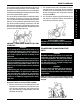
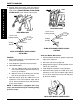
SAFETY/HANDLING The second assistant should be positioned at the front of the wheelchair lifting upward on a non-removable (nondetachable) part of the wheelchair frame when lifting the wheelchair and stabilizing the wheelchair when the wheelchair is being lowered to the ground. 2.
SAFETY/HANDLING S A F E T Y & H A N D L I N G Position the wheelchair as close as possible along side the seat to which you are transferring, with the front casters pointing toward it. Engage wheel locks. Shift body weight into seat with transfer. CENTER OF GRAVITY During independent transfer, little or no seat platform will be beneath you. Use a transfer board if at all possible.
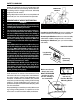
SAFETY/HANDLING REACHING, LEANING - BACKWARDS FUNCTIONAL REACH FROM A WHEELCHAIR WARNING DO NOT lean over the top of the back upholstery. This will change your center of gravity and may cause you to tip over. The approximate reach-limit values shown in the accompanying graph were derived on the basis of a sample of 91 male and 36 female subject wheelchair users. Note the difference between the maximum and the comfortable reach limits, a subjective but important consideration in design.
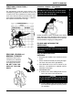
SAFETY/HANDLING S A F E T Y 5. Engage both wheel locks, open the footrest/ legrest for clearance and transfer into the wheelchair. Refer to TRANSFERRING TO AND FROM OTHER SEATS in this section of the manual. & H A N D L I N G RECLINERS ONLY Cover of the Folding Handle RECLINERS ONLY To Fold Cover of the Folding Handle Folding Handle To Fold Folding Handle To Unfold To Unfold SLING SEAT MODEL WHEELCHAIRS FOLDING SLING SEAT MODEL WHEELCHAIRS UNFOLDING Solid Seat Model Wheelchairs FOLDING. 1.
FEATURES FEATURES FOLDING BACK ANTERIOR OR POSTERIOR DIRECTION RECLINE ADJUSTABLE BACK o o 20 POSTERIOR TO 10 ANTERIOR RECLINE "T", CANTILEVER OR DUAL POINT ADJUSTABLE HEIGHT ARMS "T" SHOWN ADJUSTABLE OR FIXED HEIGHT BACK GROWABLE WITH MODULAR CROSSBRACES - 12-18-INCH SEAT DEPTHS SQUARED OFF TUBING FOR BACK CANES ONE-PIECE SIDE FRAMES SHORT, MEDIUM OR LONG DEPTH ADJUSTABLE BACK ALL ACTION FRONT RIGGINGS MULTI-POSITION, EXTENDED MULTI-POSITION OR OFFSET AXLE MOUNTING PLATES 20, 22 OR 24-INCH REAR
SPECIFICATIONS SPECIFICATIONS S P E C I F I C A T I O N S ALLEGRO PHYSICAL SPECIFICATIONS Overall Width: OPEN - Seat Width plus approximately 9-inches CLOSED - 14-inches (with back upholstery) Overall Depth (w/o front riggings): 25-inches (20-inch rear wheels and casters in trailing position) to 35-inches (24-inch rear wheels and casters in leading position) Frame Depth: Short - 14-inches, Medium - 16-inches, Long - 18-inches Seat Width: 12-18-inches for Standard Folding Frames and 12-16-inches -
PACKAGING/HANDLING PACKAGING Accessory Carton Accessory Carton ALLEGRO FOLDING FRAMES WITH AND WITHOUT SEAT RAILS P A C K A G I N G ALLEGRO RIGID FRAME HANDLING UNPACKING INSPECTION 1. Check for any obvious damage to the carton or its contents. If damage is evident, notify your Dealer/Carrier. 1. Examine exterior of the Allegro for nicks, dents, scratches or other damages. Inspect all components. If damage is evident, notify your Dealer/ Carrier. 2. Remove all loose packing from the carton. 3.
SAFETY INSPECTION CHECK LIST SAFETY INSPECTION CHECKLIST S A F E T Y I N S P E C T I O N NOTE: Twice a year take your wheelchair to a qualified dealer for a thorough inspection and servicing. Regular cleaning will reveal loose or worn parts and enhance the smooth operation of your wheelchair. To operate properly and safely, your wheelchair must be cared for just like any other vehicle. Routine maintenance will extend the life and efficiency of your wheelchair.
TROUBLESHOOTING/MAINTENANCE TROUBLESHOOTING CHAIR VEERS RIGHT X X CHAIR SLUGGISH CASTERS VEERS TURN OR FLUTTERS LEFT PERFORMANCE X X X X X X SQUEAKS LOOSENESS CHAIR AND IN CHAIR 3 WHEELS RATTLES X X X X SOLUTIONS If pneumatic, check tires for correct and equal pressure. Check for loose stem nuts and bolts. Check that both casters contact the ground at the same time. MAINTENANCE MAINTENANCE SAFETY PRECAUTIONS WARNING Do not use the wheelchair unless it has the proper tire pressure (p.s.i.).
PROCEDURE 1 FRONT RIGGINGS This Procedure includes the following: Pivot Slide Tube Height Adjustment (FIGURE 2) Installing Footrests F R O N T R I G G I N G S 1. Remove any accessories that are attached to the footrests. Adjusting Footrest Height Installing 3-inch Extension 2. Remove the hex screw and coved washer and position the footrest assembly to the desired height. Installing Elevating Legrests 3.
FRONT RIGGINGS PROCEDURE 1 INSTALLING 3-INCH EXTENSION (FIGURE 4) NOTE: Make sure to note position of hardware before disassembly of the footrest. NOTE: If using ANY type of extension with the ADJUSTABLE ANGLE FOOTPLATE, refer to INSTALLING/ADJUSTING ADJUSTABLE ANGLE FLIP-UP FOOTPLATES in this section of the manual. 1. Remove any accessories that are attached to the footrests. NOTE: The footplate will be on the inside of the wheelchair when locked in place. 4. Repeat STEPS 1-3 for the opposite legrest.
PROCEDURE 1 FRONT RIGGINGS Adjusting Calfpads F R O N T R I G G I N G S 1. To adjust the calfpad, turn pad towards the outside of the wheelchair. 2. Slide the calfpad up or down until the desired position is obtained. 3. To secure the calfpad, turn the calfpad towards the inside of the wheelchair. NOTE: The settings for positioning the adjustable angle flip-up footplates on the half-clamps may vary for each footplate. 1.
FRONT RIGGINGS PROCEDURE 1 REPLACING SECTOR BLOCK (FIGURE 10) 1. Remove the hex screw and washer that secure the existing sector block to the wheelchair frame. 3. Remove the phillips bolt and locknut that secure the heel loop to the footplate. 4. Slide heel loop over the pivot tube. 2. Position the new sector block on the wheelchair frame. Make sure the locking pin is facing UP. 5. Replace heel loop. 3. Secure the new sector block to the wheelchair frame with the existing hex screw and washer.
PROCEDURE 2 ARMS NOTE: If desired, locking pins can be installed to secure the "T" arm brackets to the wheelchair frame, as shown in FIGURE 1. This Procedure Includes the Following: Installing the "T" Arm Sockets Installing/Removing the "T" Arms 6. Repeat STEPS 2-6 for the opposite side of the wheelchair. Adjusting the "T" Arms Adjusting the Transfer Assists and/or Side Guards "T" Arms A R M S 7. Install the "T" arms into the "T" arm sockets.
ARMS PROCEDURE 2 B. Loosen - Loosening the set screws on the outside "T" arm post will make it easier to move the inside "T" arm post up and down. Removing 1. Press in on the locking lever and lift the "T" arm straight up and out of the "T" arm socket. NOTE: If the "T" arm does not slide up and down in the "T" arm socket as desired, adjust the "T" arm socket. Refer to ADJUSTING THE "T" ARMS in this section of the manual. 3.
PROCEDURE 2 ARMS 3. Reposition the arm tube on the "T" arm post: A. Desk Length Arms - to one (1) of three (3) positions depending on the desired arm pad depth. B. Full Length Arms - to one (1) of five (5) positions depending on the desired arm pad depth. A R M S NOTE: Additional positions are obtainable by turning the arm tube 180o. 4. Re-secure the arm tube to the "T" arm post with the two (2) socket screws. 5. Reattach the arm pad to the arm tube with the two (2) phillips screws. 6.
ARMS PROCEDURE 2 3. Move the bottom clamp to one (1) of three (3) mounting holes in the side guard. 3. Remove the existing locking lever and spring from the bottom bracket. NOTE: The middle mounting hole is the standard mounting position for rigid wheelchairs. NOTE: Inspect the spring and replace if necessary. NOTE: The bottom mounting hole is the standard mounting position for folding wheelchairs. NOTE: The top mounting hole is an optional mounting position for folding or rigid wheelchairs. 4.
PROCEDURE 2 ARMS 2. Slide the bottom hex bolt (w/coved washer) through the adjustment plate and back cane. USING/INSTALLING/HEIGHT ADJUSTMENT/CORRESPONDING ARM ADJUSTMENT TO BACK ANGLE CANTILEVER ARMS 3. Securely tighten the cantilever arm to the wheelchair with two (2) locknuts and washers. NOTE: The cantilever arms are designed for use with the fixed height back canes only. A R M S Using (FIGURE 9) 4. Adjust the angle of the cantilever arm, if necessary.
ARMS PROCEDURE 2 3. Refer to FIGURE 6 to determine the mounting hole in the adjustment plate that will be used to correspond to the back angle. ARM PAD DEPTH ADJUSTMENT/ REPLACEMENT - CANTILEVER ARMS (FIGURE 13) NOTE: Back angles of 105o and 110o will use the same arm adjustment plate mounting holes. Adjustment 4. Securely tighten the locking pin and washer to the adjustment plate with a locknut. 1.
PROCEDURE 2 ARMS INSTALLING FABRIC CLOTHING GUARDS (FIGURE 14) 5. Determine the necessary position for the rigid side guard. 1. Remove the seat cushion, if necessary. 6. Securely tighten the two (2) half clamps together with the socket screw. Socket Screw Washer 2. Secure the fastening straps of the fabric clothing protectors to the seat upholstery. Unthreaded Half Clamp 3. Reinstall the seat cushion, if necessary. A R M S 4.
ARMS PROCEDURE 2 Height Adjustment Lever Locked (DOWN VERTICAL) 3. Move the rear arm socket, nylon shim and rear arm socket mount to the position determined in STEP 1. 4. Reinstall the rear arm socket, nylon shim and rear arm socket mount onto the wheelchair with the hex bolt, washer and locknut. Refer to FIGURE 13 for correct orientation. Unlocked (UPHORIZONTAL) 5. Repeat STEPS 1-4 for the opposite side of the wheelchair.
PROCEDURE 3 BACK This Procedure Includes the Following: REPLACING BACK UPHOLSTERY Folding/Unfolding the Back Adjusting the Back Height NOTE: If the back upholstery HEIGHT is being changed, the back canes may also have to be changed. Refer to ADJUSTING THE BACK HEIGHT in this section of the manual. Replacing the Locking Mechanism in the Back Cane Standard Back Upholstery (FIGURE 2) Replacing Back Upholstery B A C K Changing the Back Angle Repositioning the Back (Changing Seat Depth) 1.
BACK PROCEDURE 3 2. Slide each section (anchor loop/adjuster strap) of the adjustable back upholstery with the grommet hole facing the rear of the wheelchair. 3. Secure the adjustable back upholstery to the back posts with the mounting screws. NOTE: Clean the upholstery with warm water and mild detergent to remove superficial soil.
PROCEDURE 3 BACK The top two (2) straps would be left looser to allow the upper body to lean back over the upholstery to fight gravity. This configuration may enable the back canes to be lowered for a quad. In another instance, you might loosen all of the straps and allow the end-user to sink all the way back into the wheelchair. B A C K Every person will be different. Let the therapist experiment with different positions and then decide. It is easy to change. THE BACK UPHOLSTERY COVER.
BACK PROCEDURE 3 Recliner Back Upholstery (FIGURE 10) 10o -15o Angle 1. Remove the ten (10) or twelve (12) phillips screws and washers (depending on back height) that secure the back upholstery to the back canes. P.S.I.S. 2. Remove existing back upholstery from back canes. 3. Install new back upholstery onto the back canes.
PROCEDURE 3 BACK WARNING DO NOT overtighten hex bolts. Overtightening hex bolts will prohibit the free movement of the back canes, preventing the back canes from locking properly. WARNING The back canes MUST be fastened securely to the seat frame BEFORE using the wheelchair. B A C K DO NOT overtighten hex bolts. Overtightening hex bolts will prohibit the free movement of the back canes, preventing the back canes from locking properly. 3.
BACK PROCEDURE 3 8. Remove the existing back canes from the recliner brackets. WARNING The back canes MUST be fastened securely to the seat frame BEFORE using the wheelchair. 9. Position the new back canes on the recliner brackets and tighten securely with the socket bolts, coved washers, washers and locknuts. 10. Position the actuator housings on the new back canes and tighten securely with the socket bolts, washers and locknuts. 14.
PROCEDURE 3 BACK 2. Remove the rear hex bolt, washer and locknut that secure the back angle plates to the wheelchair frame (FIGURE 15). CHANGING THE BACK ANGLE B A C K WARNING The seat height, seat depth, back angle, seating system, size and position of the rear wheels, as well as the user condition directly relate to the stability of the wheelchair. Any change to one (1) or any combination of the seven (7) may cause the wheelchair to decrease in stability.
BACK PROCEDURE 3 5. Reinstall the hex bolts that secure the back angle plates to the wheelchair frame. Make sure the back is at the desired angle. NOTE: Make sure the four (4) back angle plates are at the same angle BEFORE using the wheelchair 6. Secure the back angle brackets to the wheelchair frame with the washers and locknuts. 7. Reinstall the rear wheels onto the wheelchair. Refer to REMOVING/INSTALLING REAR WHEELS in PROCEDURE 6 of this manual.
PROCEDURE 3 BACK 4. Position the recliner brackets on the wheelchair frame at the position determined in STEP 3. Folding Push Handle Back Cane 5. Reinstall the hex bolts, washers and locknuts through the recliner brackets and wheelchair frame and tighten securely. Refer to FIGURE 19 for correct hardware orientation. B A C K 6. Reinstall the rear wheels onto the wheelchair. Refer to REMOVING/INSTALLING REAR WHEELS in PROCEDURE 6 of this manual.
SEAT PROCEDURE 4 This Procedure Includes the Following: Replacing Seat Upholstery Changing/Repositioning Seat Rails Repositioning the Crossbraces Changing Seat Width WARNING After adjustments and before use, make sure all attaching hardware is securely tightened. REPLACING SEAT UPHOLSTERY (FIGURE 1) NOTE: The following procedure is for standard folding frames only. 1. Remove the phillips screws that secure the existing seat upholstery to the crossbraces. 2.
PROCEDURE 4 SEAT REPOSITIONING THE CROSSBRACES (FIGURE 3) S E A T CHANGING SEAT WIDTH WARNING The following procedure must be performed by an authorized Invacare dealer or qualified technician. WARNING The seat height, seat depth, back angle, seating system, size and position of the rear wheels, as well as the user condition directly relate to the stability of the wheelchair. Any change to one (1) or any combination of the seven (7) may cause the wheelchair to decrease in stability.
SEAT PROCEDURE 4 Hex Bolt Locknut Seat Rail Crossbrace Locknut Hex Bolt Hex Bolt Wheelchair Frame Pivot Link Note orientation of hex bolt, bushing, washers, coved washers and locknut for installation of new crossbraces. Lower Crossbrace Saddle Self-Tapping Screw and Washer FIGURE 4 - CHANGING SEAT WIDTH - STANDARD FOLDING FRAMES Folding Frames Without Seat Rails (FIGURE 5) 1. Remove upholstery or seating system from the wheelchair. Refer to REPLACING BACK UPHOLSTERY in PROCEDURE 3 of this manual.
PROCEDURE 4 SEAT Hex Bolt Crossbrace Pivot Bracket Seat Width Holes Locknut Draw Cord Locknut S E A T Link Stop Pivot Link Hex Bolt Crossbrace Note orientation of hex Bolt, bushing, washers, coved washers and locknut for installation of new crossbraces. Hex Bolts and Locknuts Wheelchair Frame Crossbrace Lower Crossbrace Saddle Self-Tapping Screw and Washer FIGURE 5 - CHANGING SEAT WIDTH - FOLDING FRAMES WITHOUT SEAT RAILS Rigid Frames (FIGURE 6) 1.
CASTERS PROCEDURE 5 This Procedure Includes the Following: REPLACING FRONT FORK (FIGURE 2) Replacing/Repositioning/Installing Front Caster Assemblies 1. Remove the front caster assemblies from the wheelchair. Refer to REPLACING/REPOSITIONING/INSTALLING FRONT CASTER ASSEMBLIES in this section of the manual. Replacing Front Fork Repairing/Replacing Front Caster Tire/Tube o 90 Adjustment of the Caster Headtubes Caster Headtube Mounting Adjustments Installing Quick-Release Casters 2.
PROCEDURE 5 CASTERS 5. Move the caster headtube back and forth until the caster headtube is perpendicular to the ground/ floor. REPLACING/REPAIRING FRONT CASTER TIRE/TUBE C A S T E R S WARNING Replacement of front caster tire or tube MUST be performed by an authorized Invacare dealer or qualified technician. 6. While holding the caster headtube perpendicular to the ground/floor, securely tighten the adjustment cam to the caster headtube. 7.
CASTERS 8. Rotate the adjustment cam until it sits flush in the channel of the caster headtube. NOTE: An indexing notch has been put on the adjustment cam to help determine the position of the adjustment cam on the opposite caster headtube. 9. Reinstall the washer and locknut that secure the adjustment cam to the caster headtube. 10. Repeat STEPS 2-9 for the opposite side of the wheelchair.
PROCEDURE 5 CASTERS INSTALLING QUICK-RELEASE CASTERS (FIGURE 6) C A S T E R S WARNING Make sure the detent pin of the quick-release caster headtube cap is fully released BEFORE operating the wheelchair. WARNING Pull on quick-release casters each time BEFORE using the wheelchair to make sure they are securely locked onto the wheelchair frame. There are several configurations of the quick release caster. If caster fork stem DOES NOT look like the drawing in FIGURE 6 when installed, DO NOT USE.
REAR WHEELS This Procedure includes the following: Removing/Installing Rear Wheels Adjusting the Quick-Release Axle Installing the Quad-Release Axle Adjusting the Quad-Release Handle PROCEDURE 6 NOTE: During contact activities, Invacare recommends inserting quick-release axles with the head end to the inside of the wheelchair to prevent accidental release. Permanent Axles Installing Projection Handrims 1. Remove the hex screw, axle spacer and locknut that secure the rear wheel to the axle mounting plate.
PROCEDURE 6 R E A R W H E E L S REAR WHEELS WARNING Make sure the detent pin and locking pins of the quick-release axle are fully released BEFORE operating the wheelchair. WARNING Make sure the detent pin and locking pins of the quad-release axle are fully released BEFORE operating the wheelchair. Keep locking pins clean. Keep locking pins clean. 5. Reinstall rear wheel onto the wheelchair. 6.
REAR WHEELS PROCEDURE 6 WARNING Make sure the detent pin and locking pins of the quad-release axle are fully released BEFORE operating the wheelchair. WARNING Make sure detent pin and locking pins of the quick/quad-release axles are fully released BEFORE operating the wheelchair. Keep locking pins clean. 7. Reinstall rear wheel to the wheelchair. Refer to REMOVING/INSTALLING REAR WHEELS in this section of the manual. 6.
PROCEDURE 6 REAR WHEELS 5. Reinstall rear wheel to the wheelchair. Refer to REMOVING/INSTALLING REAR WHEELS in this section of the manual. R E A R W H E E L S 6. If the locking pins of the quick/quad-release axles are not protruding past the inside of the axle bushing or there is too much movement of the rear wheel assembly in a back and forth position, refer to ADJUSTING THE QUICK-RELEASE AXLE or ADJUSTING THE QUAD-RELEASE HANDLE in this section of the manual. 7.
REAR WHEELS PROCEDURE 6 WARNING DO NOT inflate tire until it is completely assembled. WARNING Wheel locks MUST be adjusted BEFORE using the wheelchair. 7. Inflate the tire to the correct psi rating on the sidewall of the tire. WARNING Make sure detent pin and locking pins of the quick/ quad-release axles are fully released BEFORE operating the wheelchair. 8. Reinstall rear wheel to the wheelchair. 9.
PROCEDURE 6 REAR WHEELS NOTE: Make sure the number of threads showing beyond the outside jam nut is the SAME for both rear wheels. This will help avoid a "3-wheeling" situation. R E A R W H E E L S 7. Adjust the wheel locks. Refer to ADJUSTING THE WHEEL LOCKS in PROCEDURE 7 of this manual. 8. If wheelchair is equipped with anti-tippers, adjust to maintain proper clearance. Refer to ADJUSTING THE ANTI-TIPPERS in PROCEDURE 7 of this manual.
WHEEL LOCKS/ANTI-TIPPERS PROCEDURE 7 3. Measure the distance between the WHEEL LOCK SHOE and the REAR WHEEL. This Procedure includes the following: Adjusting the Wheel Locks 4. Slide the wheel lock along the wheelchair until the measurement is between 5/32 and 5/16-inches. Wheel Lock Extension Handle Installation Installing/Adjusting the Anti-tippers 5. Tighten the wheel lock to the wheelchair frame. 6. Repeat this procedure for the opposite wheel lock.
PROCEDURE 7 WHEEL LOCKS/ANTI-TIPPERS 8. Pull the elastic cord back down into the wheel lock extension handle. W H E E L L O C K S 2. Adjust the anti-tippers. Refer to ADJUSTING THE ANTI-TIPPERS in this section of the manual. 9. Reinstall the black rubber tip onto the wheel lock extension handle. 10. Slide the wheel lock extension handle over the existing wheel lock handle.
RECLINER PROCEDURE 8 This Procedure Includes the Following: WARNING ALWAYS engage both wheel locks while reclining or inclining (reverse recline) the wheelchair. Recliner Operation Adjusting the Recliner Cables When returning the occupant of the wheelchair to the full upright position, more body strength will be required for approximately the last twenty (20) degrees of incline (reverse recline). Make sure to use proper body mechanics (use your legs) or seek assistance to avoid injury.
PROCEDURE 8 RECLINER 6. SLOWLY, squeeze the handles of the recliner cable assemblies and allow the back to recline to the desired angle. 7. When the back reaches desired angle, slowly release the handles of the recliner cable assemblies. R E C L I N E R 8. To return the back to the full upright position, reverse the above steps keeping in mind proper body mechanics. 7. Unscrew the fitting end of the existing recliner cable from the trigger release lever. 8.
RECLINER PROCEDURE 8 5. While holding the cable locking collar and locking nut, tighten the cable locking nut against the cable locking collar. 5. Finger tighten jam nut on the new gas cylinder until it bottoms out on the cylinder rod. WARNING Screw the rod of the gas cylinder into the actuator housing ONLY until the actuator is pointing straight out of the actuator housing. 6. Reposition the trigger release lever on the back cane. 7.
PROCEDURE 8 R E C L I N E R RECLINER 7. Tighten the jam nut on the rod of the new gas cylinder that secures the gas cylinder to the actuator housing. ● COUNTERCLOCKWISE - Turning the cable adjusting nut counterclockwise will loosen the recliner cable. 8. Line up the mounting holes of the gas cylinder and the bracket of the back cane. NOTE: If the recliner cable is too loose, the gas cylinders will not work. 9.
SEAT-TO-FLOOR PROCEDURE 9 This Procedure includes the following: Front Seat-to Floor Height (FIGURE 2) Seat-To-Floor Height Determination NOTE: The front seat-to-floor heights are approximate to +1/4-inch.
PROCEDURE 9 SEAT-TO-FLOOR After determining front caster headtube position and seatto-floor height desired, refer to CASTER HEADTUBE MOUNTING ADJUSTMENTS in PROCEDURE 5 of this manual to reposition the caster headtube on the wheelchair frame. CHANGING SEAT-TO-FLOOR HEIGHT Rear Seat-to-Floor Height S E A T T O F L O O R WARNING NEVER use the Standard Multi-Position or Offset Multi-Position axle plates with the recliner option.
SEAT-TO-FLOOR PROCEDURE 9 AXLE MOUNTING PLATE POSITIONS FOR 20, 22 or 24-INCH REAR WHEELS Refer to the following figures to determine the obtainable rear seat-to-floor height for 20, 22 or 24-inch rear wheels: NOTE: The rear seat-to-floor heights are based on pneumatic tires and pneumatic tires with flat free inserts. If wheelchair is equipped with urethane tires, subtract 1/4-inch from the measurements listed below. All heights are approximate to +1/4-inch due to tire wear and air pressure.
PROCEDURE 9 SEAT-TO-FLOOR INLINE CASTER HEADTUBE FRONT SEAT-TO-FLOOR HEIGHTS S E A T T O Refer to the following figures to determine the obtainable front seat-to-floor (S-T-F) height for Inline Caster Headtubes with 3, 5, 6 or 8-inch casters: NOTE: All measurements are in inches. The front seat-to-floor heights are approximate to +1/4-inch.
SEAT-TO-FLOOR PROCEDURE 9 OFFSET CASTER HEADTUBE FRONT SEAT-TO-FLOOR HEIGHTS Refer to the following figures to determine the obtainable front seat-to-floor (S-T-F) height for Offset Caster Headtubes with 3, 5, 6 or 8-inch casters: NOTE: All measurements are in inches. The front seat-to-floor heights are approximate to +1/4-inch.
PROCEDURE 10 S E A T D E P T H SEAT DEPTH This Procedure includes the following: SEAT DEPTH DETERMINATION (FIGURE 1) Seat Depth Determination Seat depth is determined by measuring the distance between the front of the back cane and the front of the seat rail.
SEAT DEPTH PROCEDURE 10 SEAT DEPTH CHECKLIST ❑ 1. Review the charts on the following pages to determine the proper back, seat rail and crossbrace position for the desired seat depth. NOTE: The following seat depths shown are the most common seat depths available. ❑ 2. After determining the back position for the necessary seat depth, refer to REPOSITIONING THE BACK (CHANGING SEAT DEPTH) in PROCEDURE 3 of this manual.
PROCEDURE 10 SEAT DEPTH BACK, SEAT RAIL AND CROSSBRACE POSITIONS FOR 12-INCH SEAT DEPTH S E A T NOTE: The following charts are shown with non-recliner back hardware only for clarity. The back, seat rail and crossbrace positions are the same for recliner wheelchairs.
SEAT DEPTH PROCEDURE 10 BACK, SEAT RAIL AND CROSSBRACE POSITIONS FOR 13-INCH SEAT DEPTH NOTE: The following charts are shown with non-recliner back hardware only for clarity. The back, seat rail and crossbrace positions are the same for recliner wheelchairs.
PROCEDURE 10 SEAT DEPTH BACK, SEAT RAIL AND CROSSBRACE POSITIONS FOR 14-INCH SEAT DEPTH S E A T NOTE: The following charts are shown with non-recliner back hardware only for clarity. The back, seat rail and crossbrace positions are the same for recliner wheelchairs.
SEAT DEPTH PROCEDURE 10 BACK, SEAT RAIL AND CROSSBRACE POSITIONS FOR 15-INCH SEAT DEPTH NOTE: The following charts are shown with non-recliner back hardware only for clarity. The back, seat rail and crossbrace positions are the same for recliner wheelchairs.
PROCEDURE 10 SEAT DEPTH BACK, SEAT RAIL AND CROSSBRACE POSITIONS FOR 16-INCH SEAT DEPTH NOTE: The following charts are shown with non-recliner back hardware only for clarity. The back, seat rail and crossbrace positions are the same for recliner wheelchairs.
SEAT DEPTH PROCEDURE 10 BACK, SEAT RAIL AND CROSSBRACE POSITIONS FOR 18-INCH SEAT DEPTH NOTE: The following charts are shown with non-recliner back hardware only for clarity. The back, seat rail and crossbrace positions are the same for recliner wheelchairs.
NOTES NOTES N O T E S 70
LIMITED WARRANTY LIMITED WARRANTY PLEASE NOTE: THE WARRANTY BELOW HAS BEEN DRAFTED TO COMPLY WITH FEDERAL LAW APPLICABLE TO PRODUCTS MANUFACTURED AFTER JULY 4, 1975. This warranty is extended only to the original purchaser/user of our products. This warranty gives you specific legal rights and you may also have other legal rights which vary from state to state.
Invacare Corporation www.invacare.com One Invacare Way Elyria, Ohio USA 44036-2125 800-333-6900 Technical Support 800-832-4707 Invacare is a registered trademark of Invacare Corporation © 1999 Invacare Corporation Form No. 96-100 P/N 1061057 Rev.