Owner's Operator And Maintenance Manual ® Excelerator Li'l Excelerator Excelerator XLT Excelerator XLT 2000 DEALER:THIS MANUAL MUST BE GIVEN TO THE USER OF THE WHEELCHAIR. USER: BEFORE USING THIS WHEELCHAIR, READ THIS MANUAL AND SAVE FOR FUTURE REFERENCE.
SPECIAL NOTES SPECIAL NOTES W A R N I N G WARNING DO NOT OPERATE THIS EQUIPMENT WITHOUT FIRST READING AND UNDERSTANDING THIS MANUAL. IF YOU ARE UNABLE TO UNDERSTAND THE WARNINGS, CAUTIONS AND INSTRUCTIONS, CONTACT YOUR INVACARE DEALER OR INVACARE CUSTOMER SUPPORT AT (800) 532-8677 BEFORE ATTEMPTING TO USE THIS EQUIPMENT - OTHERWISE INJURY AND/OR EQUIPMENT DAMAGE MAY RESULT.
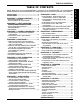
TABLE OF CONTENTS TABLE OF CONTENTS NOTE: When using the term EXCELERATOR, it will pertain to the EXCELERATOR, LI'L EXCELERATOR EXCELERATOR XLT and EXCELERATOR XLT 2000 except when the instructions specifically note otherwise. PROCEDURE 7 - CHAIN ..................................... 20 SPECIAL NOTES ........................................................ 2 SPECIFICATIONS ....................................................... 4 SAFETY INSPECTION CHECKLIST ................................
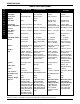
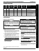
SPECIFICATIONS SPECIFICATIONS S P E C I F I C A T I O N S Seat Width: 14 to 20-inches 12 or 14-inches 14 to 20-inches EXCELERATOR XLT 2000 14 to 20-inches Seat Depth: 15 12 or 14-inches 15-inches 15-inches Seat-to-Floor (approx.): Fixed 20/18-inches Fixed 17.5/15.5 inches Fixed 12.5-inches Fixed 12.
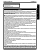
GENERAL GUIDELINES PROCEDURE 1 This Procedure Includes the Following: Operating Information Safety/Handling of Excelerator OPERATING INFORMATION WARNING Wear your helmet at ALL times when riding the Excelerator. The bicycle must be adjusted to fit the rider. Check the seat position, back height, quick release threaded axles, footrest height, hand crank adjustment for smooth operation of your Excelerator. Before riding your Excelerator, check your brakes.
PROCEDURE 1 GENERAL GUIDELINES WARNING G E N E R A L G U I D E L I N E S TIRE PRESSURE DO NOT use your Excelerator unless it has the proper tire pressure (p.s.i.). DO NOT overinflate the tires. Failure to follow these suggestions may cause the tire to explode and cause bodily harm. DO NOT ride on a flat or underinflated tires. Riding on flat or underinflated tires can cause injury, as well as, damage to the tire, tube and bicycle.
PROCEDURE 1 GENERAL GUIDELINES NOTE: This activity may be performed independently provided you have adequate mobility and upper body strength. G E N E R A L Position the Excelerator on level ground and as close as possible along side the object to which you are transferring. Apply parking brake on Excelerator and secure object that you are transferring into or out of. Shift body weight onto object with transfer. During independent transfer, little or no seat platform will be beneath you.
PROCEDURE 2 SAFETY INSPECTION/TROUBLESHOOTING/MAINTENANCE This Procedure Includes the Following: S A F E T Y I N S P E C T I O N T R O U B L E S H O O T I N G Safety Inspection Checklist Troubleshooting SAFETY INSPECTION CHECKLIST NOTE: Every six (6) months, take your Excelerator to a qualified technician for a thorough inspection and servicing. Regular cleaning will reveal loose or worn parts and enhance the smooth operation of your Excelerator.
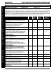
PROCEDURE 2 SAFETY INSPECTION/TROUBLESHOOTING/MAINTENANCE TROUBLESHOOTING VEERS RIGHT VEERS LEFT X X SLUGGISH WHEEL TURN OR FLUTTERS PERFORMANCE X X X X SQUEAKS AND RATTLES X LOOSENESS IN EXCELERATOR SOLUTIONS Check tires for correct and equal pressure. X X Check for loose axle nuts. X X Check spokes and nipples. X X Check chain for proper tension and adjustment. X Check that goose neck fittings are secure.
PROCEDURE 3 A S S E M B L Y P R O C E D U R E S ASSEMBLY PROCEDURES This Procedure Includes the Following: 1. Secure and adjust rear wheels (PROCEDURE 4). Excelerator/Li'l Excelerator Assembly Procedures 2. Secure the fork assembly (PROCEDURE 5). Excelerator XLT/XLT 2000 Assembly Procedures 3. Secure and adjust tension spring (PROCEDURE 5). WARNING 4. Secure and adjust hand crank assembly (PROCEDURE 5).
PROCEDURE 3 ASSEMBLY PROCEDURES EXCELERATOR XLT/XLT 2000 ASSEMBLY PROCEDURES (FIGURE 2) 1. Secure and adjust rear wheels (PROCEDURE 4). NOTE: Invacare recommends that the following procedures be performed by a qualified technician. 4. Adjust the optional cantilever brake cable (PROCEDURE 8). 2. Adjust hand crank assembly (PROCEDURE 5). 3. Adjust chain (PROCEDURE 7). 5. Adjust parking brake (PROCEDURE 8). Tools required: 6. Adjust back height and/or angle (PROCEDURE 9).
PROCEDURE 4 R E A R W H E E L S REAR WHEELS 5. Reinstall rear wheel on the Excelerator. This Procedure includes the following: Installing/Adjusting the Rear Wheels and QuickRelease Axles Installing the Rear Wheels with Threaded Axle Option - Excelerator XLT/XLT 2000 Tire/Tube Replacement and Tuning/Replacement of Spokes Tire Pressure Determining/Adjusting Toe In/Toe Out Replacing Camber Inserts 6. Tilt Excelerator onto either rear wheel and spin raised wheel.
REAR WHEELS PROCEDURE 4 2. Measure the distance between the center lines at the rear and front of the rear wheels at approximately 12inches from the ground/floor (FIGURE 3). Adjusting Toe In/Toe Out NOTE: For optimum accuracy, perform STEP 2 with the wheelchair occupied. 3. Determine the difference between the two (2) measurements. If the difference between the two (2) measurements is GREATER than 1/2-inch (0 + 1/ 4-inch for maximum rollability), one (1) of two (2) conditions exists: a.
PROCEDURE 5 FORK/SPRING/CRANK This Procedure includes the following: Ball Bearings Tension Spring Installation / Hand Crank Assembly Installation S P R I N G EXCELERATOR XLT/XLT 2000: / C R A N K Locknut EXCELERATOR/LI'L EXCELERATOR: F O R K Goose Neck Front Frame Opening Fork Assembly Installation Eye Bolt Ball Bearing Housing Washer Fork Assembly Fork /Crank Assembly Replacement Tension Spring Tension Spring or Road Crown Compensator Replacement/Adjustment Adjustable Chain Idler Eye Bol
FORK/SPRING/CRANK PROCEDURE 5 EXCELERATOR XLT/XLT 2000 FORK/CRANK ASSEMBLY REPLACEMENT (FIGURE 3) 2. Loosen, but do not remove the two (2) socket screws that secure the crank handles to the existing fork. NOTE: Invacare recommends that the following procedure be performed by a qualified technician. 4. Remove the chain from the crank handles. 1. Note the position of the crank handles. 6. Remove the two (2) socket screws and half clamp that secure the brake handle to the existing fork. 3.
PROCEDURE 5 F O R K / S P R I N G / C R A N K FORK/SPRING/CRANK 8. Note brake assembly hardware position and remove the brake assembly from the existing fork. 30. Torque the two (2) cap nuts 260-390 inch-pounds. 9. Remove the tension spring or road crown compensator from the existing fork. Refer to EXCELERATOR XLT/XLT 2000 TENSION SPRING OR ROAD CROWN COMPENSATOR REPLACEMENT in this procedure of the manual. 32. Secure the brake arm to the brake arm clamp with the hex bolt and locknut.
FORK/SPRING/CRANK PROCEDURE 5 ADJUSTING TENSION SPRING. NOTE: Adjustments should be performed BEFORE installation of the tension spring. 4. Rotate the fork to ensure the front wheel is pointing directly forward. 5. Position the fork end of the road crown compensator on the fork bolt. 1. Rotate the frame eye bolt to adjust the tension. CLOCKWISE - INCREASES tension. COUNTERCLOCKWISE - DECREASES tension. INSTALLING TENSION SPRING. 1.
PROCEDURE 6 S P E E D S H I F T E R S SPEED SHIFTERS 3. Shift gears to check for correct adjustment. This Procedure includes the following: LI'L EXCELERATOR: Three (3) Speed Shifter Cable Installation Three (3) Speed Shifter Cable Adjustment NOTE: If gears do NOT shift, increase cable tension and retest proper shifting of gears. If the chain skips a gear, loosen the cable tension until correct operation is achieved. CAUTION EXCELERATOR/EXCELERATOR - XLT: DO NOT overtighten the cables.
SPEED SHIFTERS S P E E D S H I F T E R S PROCEDURE 6 EXCELERATOR/EXCELERATOR XLT - SEVEN (7) SPEED SHIFTER CABLE INSTALLATION (FIGURE 4) 4. Ensure that there are no extreme bends in the cable and there is ample slack for the handlebars to turn without binding the cable. 5. Use a light oil and lubricate shift rod and the shift tube. NOTE: The SEVEN (7) SPEED Shifter Cable runs from the RIGHT-SIDE of the FRONT FRAME to its mounting position on the HAND CRANK Assembly Shaft. 1.
PROCEDURE 7 C H A I N CHAIN This Procedure includes the following: 5. Place chain over the top of the bottom chain tensioner. EXCELERATOR/LI'L EXCELERATOR: Chain Installation w/Seven (7) Speed Hub Chain Adjustment Chain Stay Adjustment EXCELERATOR XLT/XLT 2000: Chain Adjustment Chain Installation w/Twenty-Four (24) or TwentySeven (27) Speed Cassette 6. Attach the chain together using the master link (w/ clip) provided. EXCELERATOR/LI'L EXCELERATOR CHAIN ADJUSTMENT 1.
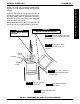
CHAIN PROCEDURE 7 Step 5 Crank Handles Hand Crank Sprocket Assembly Fork C H A I N C H A I N Socket Screws FIGURE 3 - EXCELERATOR - XLT CHAIN ADJUSTMENT EXCELERATOR XLT/XLT 2000 CHAIN INSTALLATION - TWENTYFOUR (24) OR TWENTY-SEVEN (27) SPEED CASSETTE (FIGURE 4) 1. Spread the chain out flat and run it around the chain ring on the crank and the sprocket on the hub. Step 3 NOTE: It may be necessary to turn the hand crank in a clockwise motion to position the chain on the small sprocket. 2.
PROCEDURE 8 P A R K I N G B R A K E PARKING BRAKE This Procedure includes the following: Adjustment Using Parking Brake CABLE. 1. Loosen the hex nut and turn the adjuster barrel clockwise (tighten) or counterclockwise (loosen) to adjust the cable. Retighten hex nut. Parking Brake Adjustment/Replacement WARNING BRAKE PADS. 1. Adjust the brake pad assembly so that when the parking brake is engaged the brake pads rest solely on the rim of the wheel.
BACK/SEAT PROCEDURE 9 4. Secure the top of the back upholstery to the fastening flaps ensuring the top of the back upholstery is even with the top of the back canes.
PROCEDURE 9 BACK/SEAT 3. Remove the locknuts from the threaded studs from seat rails on both sides of seat. 4. Remove seat from seat rails. B A C K / S E A T 5. Reverse STEPS 3-4 to install NEW seat onto seat rails. 6. Reverse STEPS 1-2 to install sliding seat and seat rails onto the seat frame. 6. Tighten the hex bolts and locknuts that secure the two (2) seat angle adjustment clamps to the rear seat supports securely. EXCELERATOR XLT/XLT 2000 BACK ANGLE ADJUSTMENT (FIGURE 4) 1.
UPHOLSTERY PROCEDURE 10 4. Install the new back upholstery onto the wheelchair. This Procedure includes the following: Seat Upholstery Replacement Back Upholstery Replacement 5. Securely latch the fastening flaps on the bottom of the new back upholstery to the back canes. Back Upholstery WARNING After ANY adjustments, repair or service and BEFORE use, make sure all attaching hardware is tightened securely - otherwise injury or damage may result. Upholstery MUST be inspected BEFORE each use.
PROCEDURE 11 F O O T R E S T FOOTREST This Procedure includes the following: Replacing Individual Footplates EXCELERATOR LI'L EXCELERATOR: Footrest Adjustment/Replacement 1. Remove the two (2) button screws and locknuts that secure the footrests to the footplate clamps. EXCELERATOR - XLT/XLT 2000: Footrest and Leg Guard Replacement 2. Align new footplates on the footplate clamps at the desired depth. Using/Replacing Footrest Strap 3.
FOOTREST PROCEDURE 11 EXCELERATOR XLT/XLT 2000 FOOTREST AND LEG GUARD REPLACEMENT (FIGURE 2) Footrest Replacement Footrest 1. Note the position of the existing footrest. F O O T R E S T Fork 2. Remove the hex bolt and locknut that secure the existing footrest to the fork. 3. Remove the existing footrest from the clamp on the fork. Clamp, Hex Bolt and Locknut 4. Slide the new footrest into the clamp on the fork to the position noted in STEP 1. 5. Reinstall the hex bolt and locknut. Tighten securely.
PROCEDURE 11 FOOTREST 3. Firmly connect the hook and loop portion of the footrest strap to secure the footrest strap to the inner footrest tube as shown in DETAIL "A". EXCELERATOR XLT/XLT 2000 USING/REPLACING FOOTREST STRAP 4. Wrap end of footrest strap over and around the outer footrest tube and under the inner footrest tube as shown in DETAILS "A" and "B". WARNING F O O T R E S T Footrest straps MUST be inspected BEFORE each use. Exposure to moisture (ie.
OPERATION PROCEDURE 12 Excelerator XLT Twenty-four (24) Speed (FIGURE 2) This Procedure includes the following: Hand Crank Assembly Shifting Gears Backing Up/Braking/Parking Brake Steering/Cornering Mountain Drive Option WARNING To shift gears, you MUST turn the crank forward with the chain under some tension while the bike is moving. DO NOT attempt to shift gears while bike is stationary. Shifting the chain towards the centerline of the handcycle is for climbing/accelerating and is called a downshift.
PROCEDURE 12 OPERATION Excelerator XLT 2000 Twenty-seven (27) Speed Cassette (FIGURE 3) O P E R A T I O N BACKING-UP To shift gears, you MUST turn the crank forward with the chain under some tension while the bike is moving. DO NOT attempt to shift gears while bike is stationary. Shifting the chain towards the centerline of the handcycle is for climbing/accelerating and is called a downshift. Moving the chain out or away from the centerline of the handcycle is for speed and is called an upshift. 1.
OPERATION PROCEDURE 12 Tightening Hand Crank WARNING The twenty-seven (27) speed cassette on the Excelerator XLT 2000 uses the hand brake as the primary brake. Reverse pedaling WILL NOT stop the bike. NOTE: If hand crank will not engage the chain, it will be necessary to tighten the Mountain Drive Crank nut. 1. Insert the open end of the hooked wrench (provided) around the nut between the hand crank and axle and cup tube. STEERING/CORNERING 2. Hold the hand crank and turn the wrench clockwise.
PROCEDURE 12 OPERATION Bearing Play Adjustment (FIGURE 6) Adjusting Gear Shift Push Button (FIGURE 7) NOTE: Refer to the SAFETY INSPECTION CHECKLIST to determine how often bearing play adjustment is necessary. O P E R A T I O N NOTE: This adjustment is required only if there is some play in the hand crank in a SIDE TO SIDE motion. NOTE: There will be some play in a forward/rearward motion. 1. Slightly tighten self-locking nut on the left side (sitting in the handcycle) of the hand crank.
OPTIONS PROCEDURE 13 Operating the Safety Light This Procedure includes the following: Water Bottle Installation Tow Bar Installation Safety Light Installation Computer Installation Seat Positioning Strap Installation Horizontal Handles Tri-Pin Spinning Quad Handles Gloves Safety Flag Safety Helmet 1. Press GREY button for ON/OFF. 2. Remove lens cover and slide Black switch back and forth for pulse or constant mode. Mounting the Safety Light 1. Open clip on back of safety light. 2.
PROCEDURE 13 OPTIONS SAFETY HELMET (FIGURE 1) 3. Three (3) different brackets included for different widths. 1. Secure helmet using the chin strap. 2. Ensure proper fit. O P T I O N S LATERAL SUPPORT (FIGURE 1) 4. Change bracket by removing the existing button screws and attach the new bracket with the existing button screws. 1. Position lateral support on frame as shown. 2. Secure with button screws.
WARRANTY LIMITED WARRANTY PLEASE NOTE: THE WARRANTY BELOW HAS BEEN DRAFTED TO COMPLY WITH FEDERAL LAW APPLICABLE TO PRODUCTS MANUFACTURED AFTER JULY 4, 1975. This warranty is extended only to the original purchaser/user of our products. This warranty gives you specific legal rights and you may also have other legal rights which vary from state to state.
Invacare Corporation USA One Invacare Way Elyria, Ohio USA 44036-2125 800-333-6900 www.invacare.com Invacare Top End Sports and Recreation Products 4501 63rd Circle North Pinellas Park, FL 34665 800-532-8677 Invacare and "Yes, you can" are trademarks of Invacare Corporation. © 2000 Invacare Corporation Form No. 95-124 Part No.