Service Manual Perfecto2™ Oxygen Concentrator (HomeFill® Compatible) Model IRC5PO2 (Sensored) Model IRC5P (Non-Sensored) DEALER: Keep this manual. The procedures in this manual MUST be performed by a qualified technician. For more information regarding Invacare products, parts, and services, please visit www.invacare.
WARNING DO NOT OPERATE THIS EQUIPMENT WITHOUT FIRST READING AND UNDERSTANDING THIS MANUAL. IF YOU ARE UNABLE TO UNDERSTAND THE WARNINGS, CAUTIONS, AND INSTRUCTIONS, CONTACT INVACARE TECHNICAL SERVICES BEFORE ATTEMPTING TO USE THIS EQUIPMENT OTHERWISE SERIOUS INJURY OR PROPERTY DAMAGE MAY RESULT. WARNING Invacare products are specifically designed and manufactured for use in conjunction with Invacare accessories.
TABLE OF CONTENTS TABLE OF CONTENTS SPECIAL NOTES ................................................................................ 6 FEATURES ........................................................................................ 7 TYPICAL PRODUCT PARAMETERS .................................................... 8 SECTION 1—IMPORTANT SAFEGUARDS .......................................... 10 Important Safeguards ..................................................................................................
TABLE OF CONTENTS TABLE OF CONTENTS SECTION 10—CHECK VALVES ......................................................... 46 Replacing Check Valves...........................................................................................................................46 SECTION 11—REGULATOR .............................................................. 48 Replacing Regulator..................................................................................................................................
TABLE OF CONTENTS TABLE OF CONTENTS SECTION 23—LEAK TEST ................................................................ 76 Leak Test ....................................................................................................................................................76 4 Way Valve Function Test ....................................................................................................................78 SECTION 24— ALARM TEST .........................................................
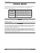
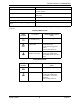
SPECIAL NOTES SPECIAL NOTES Signal words are used in this manual and apply to hazards or unsafe practices which could result in personal injury or property damage. Refer to the table below for definitions of the signal words. SIGNAL WORD MEANING DANGER Danger indicates an imminently hazardous situation which, if not avoided, will result in death or serious injury. WARNING Warning indicates a potentially hazardous situation which, if not avoided, could result in death or serious injury.
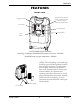
FEATURES FEATURES FRONT VIEW Oxygen Purity Indicator Lights / Fault and Power Indicator Lights (SensO2 Model Only) Oxygen Outlet Flowmeter Circuit Breaker Power Switch Hour Meter ACCESSORIES (NOT SHOWN): PreciseRX™ Pediatric Humidifier/Flowmeter Accessory ‐ IRCPF16 HomeFill home oxygen compressor ‐ IOH200 *NOTE: This outlet fitting is to be used only for filling oxygen cylinders with the HomeFill home oxygen compressor. The outlet fitting does not affect concentrator performance.
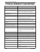
TYPICAL PRODUCT PARAMETERS TYPICAL PRODUCT PARAMETERS Electrical Requirements: 120 VAC ± 10% (132 VAC/108 VAC), 60 Hz Rated Current Input: Perfecto2 5: 3 A Sound Level: Perfecto2 5: 44 ± 2 dBA Average Altitude: Perfecto2 5 - Up to 6,000 ft. (1828 meters) above sea level without degradation of concentration levels. From 6,000 ft. (1828 meters) to 13,129 ft. (4000 meters) below 90% efficiency. *Oxygen Output Concentration Levels: All IRC5PO2/IRC5P models 95.6% to 87% at 0.
TYPICAL PRODUCT PARAMETERS Electrical: No extension cords. Placement: No closer than three inches from any wall, furniture, draperies, or similar surfaces. Tubing: 7 ft cannula with a maximum 50 ft of Crush-Proof Tubing (DO NOT pinch). Relative Humidity: 20 to 60% Time of Operation: Up to 24 hours per day. Recommended Storage and Shipping Temper- -20°F to 150°F (-29°C to 65°C), at 15-95% relative humidity.
SECTION 1—IMPORTANT SAFEGUARDS SECTION 1—IMPORTANT SAFEGUARDS Important Safeguards In order to ensure the safe installation, assembly and operation of the Perfecto2 concentrator these instructions MUST be followed. CAUTION “Caution: Federal law restricts this device to sale or rental by or on order of a physician, or any other practitioner licensed by the law of the State in which he/she practices to use or order the use of this device.
SECTION 1—IMPORTANT SAFEGUARDS Radio Frequency Interference Most electronic equipment is influenced by Radio Frequency Interference (RFI). Caution should be exercised with regard to the use of portable communications equipment in the area around such equipment. To Reduce The Risk Of Burns, Electrocution, Fire Or Injury To Persons. DO NOT come in contact with the concentrator while wet. DO NOT place or store product where it can drop into water or other liquid.
SECTION 2—INSTALLATION/SEQUENCE OF OPERATION SECTION 2—INSTALLATION/ SEQUENCE OF OPERATION Verification of Battery Free Power Loss Alarm Check the Perfecto2 concentrator for proper operating conditions. 1. If the unit has been in below‐freezing temperatures, allow it to warm up to room temperature before operating. 2. The concentrator may need to be turned on for four to five seconds to charge the Battery Free Power Loss Alarm. Connect power cord to outlet and turn the concentrator on.
SECTION 2—INSTALLATION/SEQUENCE OF OPERATION The electrical activation of the 4‐way Valve is accomplished every 8 to 15 seconds by the pressure sensor and P.C. Board electronics when the pressure reaches a set point of 21 p.s.i. (144.79 kPa) output flows 4 L/min and above or 16 p.s.i. (110.32 kPa) output flows 3 L/min and below. The time between cycles is dependent on altitude, flow rate and internal environmental factors. A P.E. valve opens just prior to the shift of the 4‐way valve.
SECTION 2—INSTALLATION/SEQUENCE OF OPERATION After five minutes, if the oxygen purity exceeds 85% ± 2%, the GREEN light will continue to illuminate. If the oxygen level is not above 85% ± 2% after the first five minutes, the system will continue to monitor the O2 and wait for a maximum of 30 minutes from start‐up to reach 85% ± 2% before activating an alarm. Environmental factors such as low voltage, high altitude, or age of the machine will affect the time required to reach 85% ± 2%.
SECTION 3—PNEUMATIC DIAGRAM SECTION 3—PNEUMATIC DIAGRAM Perfecto2 Oxygen Concentrator Ouput HEPA Filter Output Check Valve Flowmeter Patient Output Oxygen Sensor (SensO2 models Only) Pressure Regulator Pressure Sensor P.S.I. O2 P.C. Board Product Tank Check Valves Air Inlet Cabinet Filter Compressor Inlet Filter Sieve Bed P.E.
SECTION 4—TROUBLESHOOTING SECTION 4—TROUBLESHOOTING SYMPTOM PROBABLE CAUSE No Problems. Normal Operation: Internal Status Indicators: RED: Off GREEN: Off Unit plugged in, power switch on. Single beep on start up. No Problems. Power loss: Internal Status Indicators: RED: Off GREEN: Off Unit unplugged, power switch on, alarm off. No power at outlet. Power loss: Internal Status Indicators: RED: Off GREEN: Off Unit plugged in, power switch , alarm off, battery Free circuit drained. System Okay.
SECTION 4—TROUBLESHOOTING SYMPTOM Power Loss: (Continued) Internal Status Indicators: RED: Off GREEN: Off Unit plugged in, power switch, alarm off. Battery Free circuit drained Internal Power Loss Senso2: Internal Status Indicators: RED: Off GREEN: Off Alarm may or may not be on. Control Panel Indicators: RED: Off YELLOW: Off GREEN: Off Fan operates, Compressor not operating. High Pressure: Internal Status Indicators: PROBABLE CAUSE P.C. board. a. P.C. board damaged. b. Loose or damaged connector.
SECTION 4—TROUBLESHOOTING SYMPTOM PROBABLE CAUSE LOW PRESSURE: Internal Status Indicators: RED: One Flash GREEN: One Flash Or RED: One Flash GREEN: Three Flashes Compressor: a. Leaks at fittings or tubing b. Leaking or defective relief valve. c. Insufficient voltage at outlet. Control Panel Indicators: RED: On YELLOW: Off GREEN: Off Heat exchanger: a. Leak at tubing or body chamber. b. Inspect tubing and heat exchanger. d. Worn cup seals or gaskets.
SECTION 4—TROUBLESHOOTING SYMPTOM Unit not operating: Alarm: On or Off Internal Status Indicators: RED: Two Flashes GREEN: Four Flashes Or RED: Two Flashes GREEN: Five Flashes Low Concentration: NOTE: Check for O2 purity using a calibrated Oxygen Analyzer at Test Point 1 (oxygen outlet) of the concentrator. PROBABLE CAUSE P.C. board Failure. Replace P.C. board.Refer to Replacing P.C. Board on page 58. Cabinet filters dirty. Clean or replace.
SECTION 4—TROUBLESHOOTING SYMPTOM Low Concentration (Continued) PROBABLE CAUSE P.C. board: a. Shifts at wrong pressures. Flowmeter: a. Flowmeter opened beyond maximum flow rate. b. Cracked or broken fitting. c. Input tubing leaking or loose. Timing. P.E. valve: a. Bad coil. b. Restrictor blockage. Inspect P.C. board restrictor tubing for kinks or tears. Fluctuating Flow: Regulator/Flowmeter: a. Incorrectly set regulator. b. Flowmeter malfunction. Outlet HEPA filter: a.
SECTION 4—TROUBLESHOOTING SYMPTOM Unit Overheats: PROBABLE CAUSE Base exhaust vent plugged or restricted. Cabinet filters dirty or blocked. Fan: a. Leads to fan disconnected. b. Defective fan. c. Fan installed upside down. Heat exchanger: a. Dirty or plugged. b. Damaged. b. Faulty capacitor. c. Bad motor windings. d. Worn seals. e. Bad bearings. Line voltage excessive (surge). Part No 1148070 Place unit at least 3-inches from any wall.
SECTION 4—TROUBLESHOOTING SYMPTOM PROBABLE CAUSE Internal repairs required. Unit Operating, Internal Status Indicators: RED: Three Flashes GREEN: One Flash Control Panel Indicators: RED: Off YELLOW: Flashing GREEN: On Low-Flow Alarm does not System leak. activate on flows less than 0.5 L/min. Defective check valves. Perfecto2™ 22 SOLUTION Replace SensO2 circuit board. Refer to Replacing P.C. Board on page 58. Repair leak in product tank, regulator, tubing, fittings, or flow meter.
SECTION 5—CABINET SECTION 5—CABINET Removing Cabinet DANGER To prevent electrical shock, ALWAYS disconnect concentrator from electrical outlet before servicing. NOTE: For this procedure, refer to FIGURE 5.1. 1. Unplug unit. 2. Remove the four mounting screws that secure cabinet assembly to the base assembly. 3. Lift the cabinet straight up. NOTE: When required, vacuum inside of the cabinet and exposed foam insulation. 4. To re‐install cabinet, reverse STEPS 2‐3.
SECTION 6—PREVENTIVE MAINTENANCE SECTION 6—PREVENTIVE MAINTENANCE DANGER To prevent electrical shock, ALWAYS disconnect concentrator from electrical outlet before servicing. NOTE: The Perfecto2 Concentrators are specifically designed to minimize routine preventive maintenance at intervals of once per year. In places with high dust or soot levels, maintenance may need to be performed more often. The following MUST be performed at a minimum of one year in service to assure years of additional reliability.
SECTION 6—PREVENTIVE MAINTENANCE Replacing the Outlet HEPA Filter Check the Outlet HEPA Filter NOTE: The outlet HEPA filter can be checked by performing the following procedure. 1. Turn the concentrator on and adjust the flowmeter to the maximum flow of the unit. 2. Observe the flowmeterʹs flow indicator while connecting a fifty foot cannula tube to the outlet barb of the concentrator (not shown). 3. If the flow indicator fluctuates, the outlet HEPA filter may need replacement.
SECTION 6—PREVENTIVE MAINTENANCE Replacing the Compressor Inlet HEPA Filter NOTE: For this procedure, refer to FIGURE 6.3 on page 26. NOTE: Perform this procedure as needed depending upon the environment the concentrator is used in. 1. Unplug the unit. 2. Remove the filter access panel by pressing down on center tab and pulling panel out. 3. Grasp the compressor inlet HEPA filter, pull outward and up until filter is dislodged from rubber base. 4. Discard the existing compressor inlet HEPA filter. 5.
SECTION 6—PREVENTIVE MAINTENANCE 4. Remove the bottom of the manifold exhaust tube from the “F” tube. 5. Disconnect and remove the top of the manifold exhaust tube from the grommet. Top of Manifold Exhaust Tube Tie-Wrap Rubber Grommet Bottom of Manifold Exhaust Tube “F” Tube FIGURE 6.4 Replacing the Muffler Assembly 6. Push the muffler assembly down through the opening in the sound box. 7. Cut the two tie wraps around the muffler assembly. 8. Separate the muffler assembly (Detail “A”in FIGURE 6.5 ). 9.
SECTION 6—PREVENTIVE MAINTENANCE 12. Reinstall cabinet. Refer to Removing Cabinet on page 23. Top of Manifold Exhaust Tube Sound Box Rubber Grommet Tie Wraps Throttling Muffler Exhaust Canister Muffler Body 8” Tie-Wrap DETAIL “A” Throttling Muffler Assembly Exhaust Muffler Grommet Muffler Grommet Exhaust Canister 8” Tie-Wrap FIGURE 6.
SECTION 6—PREVENTIVE MAINTENANCE Cleaning the Heat Exchanger DANGER To prevent electrical shock, ALWAYS disconnect concentrator from electrical outlet before servicing. NOTE: For this procedure, refer to FIGURE 6.6. 1. Unplug unit. 2. Remove cabinet. Refer to Removing Cabinet on page 23. CAUTION Use care not to deform heat exchanger when installing, removing or cleaning. 3. Remove excess dirt using compressed air or vacuum. 4. Reinstall cabinet. Refer to Cabinet on page 23. Heat Exchanger FIGURE 6.
Perfecto2™ 30 *NOTE: Refer to Preventive Maintenance section of Service Manual. NOTE: 4,380 hours are equivalent to usage 24 hours per day, 7 days per week, for 6 months. 26,280 hours are equivalent to usage 24 hours per day, 7 days per week, for 3 years.
SECTION 7—COMPRESSOR SECTION 7—COMPRESSOR DANGER To prevent electrical shock, ALWAYS disconnect concentrator from electrical outlet before servicing. Replacing Compressor Assembly NOTE: For this procedure, refer to FIGURE 7.1 on page 32 and FIGURE 7.2 on page 33. 1. Unplug unit. 2. Remove the cabinet. Refer to Removing Cabinet on page 23. 3. Cut the tie wrap that secures the intake hose to the compressor assembly (Detail “A”). 4. Disconnect intake hose from compressor assembly (Detail “A”). 5.
SECTION 7—COMPRESSOR DETAIL “A” DETAIL “B” Tie-Wrap Brass Nut Capacitor Compressor Capacitor Wires attach here Compressor Intake Hose DETAIL “C” DETAIL “D” Mounting Screws Mounting Screws Grommets Vinyl Tube Clamp Manifold Assembly FIGURE 7.
SECTION 7—COMPRESSOR Replacing Capacitor NOTE: For this procedure, refer to FIGURE 7.2 on page 33. 1. Unplug the unit. 2. Remove the cabinet. Refer to Removing Cabinet on page 23. 3. Using needlenose pliers, disconnect the spade connectors from the capacitor terminals. 4. Cut the tie wrap that secures the capacitor to the base of the concentrator. 5. Remove the capacitor from the concentrator base. 6. Install new capacitor by reversing STEPS 3‐6. 7. Re‐install the cabinet.
SECTION 7—COMPRESSOR Rebuilding the Thomas Model 2660 Compressor DANGER To prevent electrical shock, ALWAYS disconnect concentrator from electrical outlet before servicing. NOTE: This kit is designed for rebuilding the Thomas Model 2660 Series compressor. The model number is located on the front of the compressor. Compressor numbers for this kit are 2660CE32, 2660CE37, and 2660CE50. If the compressor has a different model number than those listed, this kit will not work.
SECTION 7—COMPRESSOR CAUTION DO NOT lubricate or use oil on any moving parts. The compressor eccentric uses a precision sealed bearing. Therefore, additional lubrication is not necessary. Removing Compressor and Compressor Heads Compressor 1. Unplug concentrator and carefully remove compressor from concentrator. Refer to Replacing Compressor Assembly on page 31. Compressor Head Plate NOTE: For this procedure, refer to FIGURE 7.3. 1. Clean loose dirt from the outside of the compressor.
SECTION 7—COMPRESSOR Fan NOTE: For this procedure, refer to FIGURE 7.4. 1. Using two flat blade screwdrivers, pry the fan off of the motor shaft under the center housing. DO NOT pry under the fan blades. NOTE: Note position/orientation of fan for reassembly. Connecting Rod and Eccentric Assembly NOTE: For this procedure, refer to FIGURE 7.4. 1. Rotate shaft to align the eccentricʹs set screw with the access hole in the bottom of the compressor housing. 2.
SECTION 7—COMPRESSOR O-ring, Intake Valve Keeper and Valve Keeper Strip NOTE: For this procedure, refer to FIGURE 7.5. 1. Remove the O‐ring, intake valve flapper and valve keeper strip from the bottom of the valve plate. Discard all. Valve Flapper Screw 2. Clean the bottom of the valve plate with a clean, soft cloth. Valve Keeper Strip O-Ring Intake Valve Flapper FIGURE 7.
SECTION 7—COMPRESSOR Rebuilding the Compressor NOTE: Before reassembly, wipe any residue from all components with a clean soft cloth. Gasket NOTE: For this procedure, refer to FIGURE 7.6 on page 37. 1. Install new gasket; seating the gasket firmly in the groove at the top of the valve plate with your finger or blunt object. CAUTION Make sure that the gasket is not twisted when seated in the groove of the top of the valve plate.
SECTION 7—COMPRESSOR CAUTION DO NOT lubricate or use oil on any moving parts. The compressor eccentric uses a precision sealed bearing. DO NOT crimp the piston cup when you replace the sleeve. If the cup is crimped, it MUST be replaced. 3. With bearing side of connecting rod/eccentric assembly facing the center (motor) of the compressor, slide the assembly onto the shaft bringing it flush to the motor bearing. NOTE: Make sure the eccentric set screw is positioned over the flat of the shaft. 4.
SECTION 7—COMPRESSOR Compressor WARNING To avoid personal injury or property damage, rotate the fan by hand prior to connecting the unit to a power source. Check for suction at the air inlet by placing your finger over the port as you rotate the fan. You should feel a slight suction with each rotation of the fan. If you DO NOT feel a suction but you feel or hear a thump as you turn the fan, DO NOT connect the unit to a power source. Review the assembly procedure for possible error.
SECTION 7—COMPRESSOR COMPRESSOR PARTS LEGEND 1. Connecting Rod, Eccentric & Bearing Assembly 2. Piston Cup 3. Screw - Piston Cup Retainer 4. Piston Cup Retainer 5. Cylinder Sleeve 6 Head 7. O-Ring - Head Gasket 8. Screw - Head 9. Valve Plate Assembly 10. Valve Restraint 11. Valve Keeper Strip 12. Valve Flapper - Intake & Exhaust 13. Valve Plate 14. Screw - Valve Flapper 15. O-Ring Valve Plate 16. Fan - Gray 17. Fan - Black FIGURE 7.
SECTION 8—P.E. VALVE SECTION 8—P.E. VALVE Replacing P.E. Valve DANGER To prevent electrical shock, ALWAYS disconnect concentrator from electrical outlet before servicing. NOTE: For this procedure, refer to FIGURE 8.1 on page 43. 1. Unplug unit. 2. Remove cabinet. Refer to Removing Cabinet on page 23. 3. Remove the compressor inlet HEPA filter. Refer to Replacing the Compressor Inlet HEPA Filter on page 26. 4. Remove spade connectors from P.E. valve terminals. 5. Remove tie‐wraps from P.E. valve tubing.
SECTION 8—P.E. VALVE P.E. Valve Tubing Tie-Wrap P.E. Valve Assembly P.E. Valve Tubing “Out” Port Barb OUT Tie-Wrap Sieve Bed P.E. Valve Terminals (Spade Connectors Attach Here are not shown) FIGURE 8.1 Replacing P.E.
SECTION 9—SIEVE BEDS SECTION 9—SIEVE BEDS Replacing Sieve Beds DANGER To prevent electrical shock, AWAYS disconnect concentrator from electrical outlet before servicing. NOTE: For this procedure, refer to FIGURE 9.1 on page 45. NOTE: ALWAYS replace sieve beds in pairs to ensure that both beds are in optimum condition. 1. Unplug unit. 2. Remove cabinet. Refer to Removing Cabinet on page 23. 3. Remove compressor inlet HEPA filter. Refer to Replacing the Compressor Inlet HEPA Filter on page 26. 4.
SECTION 9—SIEVE BEDS P.E. Valve Assembly Check Valve Tubing Tie-Wraps Check Valve Tubing Tie-Wraps Tie-Wrap P.E. Valve Tubing P.E. Valve Tubing Tie Wraps Tie-Wrap Clamp Sieve Bed Reinforced Tubing attaches HERE (not shown) NOTE: Compressor Inlet HEPA Filter removed from illustration for clarity. FIGURE 9.
SECTION 10—CHECK VALVES SECTION 10—CHECK VALVES Replacing Check Valves DANGER To prevent electrical shock, ALWAYS disconnect concentrator from electrical outlet before servicing. NOTE: For this procedure, refer to FIGURE 10.1 on page 47. 1. Unplug unit. 2. Remove cabinet. Refer to Removing Cabinet on page 23. NOTE: Replace one or both check valves when performing this procedure. The check valves are one‐ way directional and can be checked by passing air through them.
SECTION 10—CHECK VALVES 8. Reinstall compressor inlet HEPA filter. Refer to Replacing the Compressor Inlet HEPA Filter on page 26. 9. Run units and check for leaks. Refer to Leak Test on page 76. 10. Reinstall cabinet. Refer to Removing Cabinet on page 23. Location of Product Tank ¼ PVC Inlet Tubing Check Valves Regulator Outlet Tubing Tie-wrap Tie-wrap Check Valves Tie-wrap Regulator Tie-wrap Flow Arrow Product Tank FIGURE 10.
SECTION 11—REGULATOR SECTION 11—REGULATOR Replacing Regulator DANGER To prevent electrical shock, ALWAYS disconnect concentrator from electrical outlet before servicing. NOTE: For this procedure, refer to FIGURE 11.1 on page 49. 1. Unplug unit. 2. Remove cabinet. Refer to Removing Cabinet on page 23. NOTE: On concentrator models with the SensO2 unit ONLY, remove the 1/8‐inch tubing to oxygen sensor housing. 3. Remove the four mounting screws that secure regulator to product tank cap. 4.
SECTION 11—REGULATOR Pressure Regulator (Top) Pressure Regulator Pressure Adjustment Screw (5/32-inch Allen Wrench) Mounting Screws Product Tank Pressure Sensor Tubing Location of Product Tank NOTE: For adjusting the regulator there is no need to remove the control panel. FIGURE 11.1 Replacing Regulator Adjusting Regulator NOTE: For this procedure, refer to FIGURE 11.1 on page 49. 1. Turn unit on (I). 2. Install pressure gauge onto oxygen outlet. NOTE: Use a 0 ‐ 30 p.s.i. pressure gauge.
SECTION 11—REGULATOR 9. Adjust until pressure reads a steady five p.s.i. ± 0.5 p.s.i. 10. Once required pressure is achieved, reinstall cabinet. Refer to Removing Cabinet on page 23. 11. Refer to Troubleshooting on page 16 if you are unable to adjust or maintain five p.s.i. ± 0.5 p.s.i. NOTE: After ten minutes of run time, retest output pressure of concentrator to insure proper operation and/or spec levels.
SECTION 12—HEAT EXCHANGER ASSEMBLY SECTION 12—HEAT EXCHANGER ASSEMBLY Replacing Heat Exchanger Assembly DANGER To prevent electrical shock, ALWAYS disconnect concentrator from electrical outlet before servicing. NOTE: For this procedure, refer to FIGURE 12.1 on page 52. NOTE: The heat exchanger assembly contains three components: heat exchanger, nine inch vinyl tube and connecting component. 1. Unplug unit. 2. Remove cabinet. Refer to Removing Cabinet on page 23.
SECTION 12—HEAT EXCHANGER ASSEMBLY DETAIL “A” Heat Exchanger Assembly Sound Box Brass Nut Compressor DETAIL “B” Vinyl Tube Manifold Assembly Clamp Sound Box FIGURE 12.
SECTION 13—CONTROL PANEL SECTION 13—CONTROL PANEL Removing Control Panel DANGER To prevent electrical shock, ALWAYS disconnect concentrator from electrical outlet before servicing. NOTE: For this procedure, refer to FIGURE 13.1 on page 54. Tools Required: • Diagonal cutters • Flathead screwdriver • ¼‐inch ratchet, ¼‐inch socket, and ¼‐inch extension • Pliers • Tie‐wraps 1. Unplug unit. 2. Remove cabinet. Refer to Cabinet on page 23. 3.
SECTION 13—CONTROL PANEL 15. Run unit and check for leaks at pressure sensor tubing on product tank cap. Refer to Leak Test on page 76 16. Reinstall cabinet. Refer to Removing Cabinet on page 23. DETAIL “A” DETAIL “B” Tie Wrap Control Panel Mounting Screws (STEP 5) Tie Wrap ¼ Tubing (STEP 6) Control Panel ¼ Tubing (STEP 7) Control Panel Circuit Breaker (STEP 9) Hour Meter (STEP 9) On/Off Switch (STEP 9) P.C. Board Mounting Screws FIGURE 13.
SECTION 14—COOLING FAN SECTION 14—COOLING FAN Replacing Cooling Fan DANGER To prevent electrical shock, ALWAYS disconnect concentrator from electrical outlet before servicing. NOTE: For this procedure, refer to FIGURE 14.1 on page 57. 1. Unplug unit. 2. Remove cabinet. Refer to Cabinet on page 23. 3. Remove control panel. Refer to Removing Control Panel on page 53. 4. Remove compressor inlet HEPA filter. Refer to Replacing the Compressor Inlet HEPA Filter on page 26. 5.
SECTION 14—COOLING FAN 15. Connect spade connectors to fan terminals on side of cooling fan (Detail “B”). 16. Move resonator housing back into position (Detail “A”). 17. Secure the resonator housing to the soundbox with the three mounting screws. Two in the top and one on the back near the bottom of the housing (Detail “A”). 18. if necessary, reconnect the intake valve on the compressor assembly. 19. Reinstall control panel. Refer to Removing Control Panel on page 53. 20.
SECTION 14—COOLING FAN DETAIL “B” DETAIL “A” Rubber Grommet Cooling Fan Mounting Screws Mounting Screw Intake Hose Resonator Housing Compressor Assembly Fan Terminals (Spade Connectors attach here) DETAIL “D” NOTE: Sieve Beds are not shown for clarity. Soundbox Cooling Fan DETAIL “C” Cooling Fan Soundbox Rubber Grommets Rubber Grommets Larger recessed area to be installed in fan. Smaller recessed area to be installed in soundbox.
SECTION 15—P.C. BOARD SECTION 15—P.C. BOARD Replacing P.C. Board DANGER To prevent electrical shock, ALWAYS disconnect concentrator from electrical outlet before servicing. CAUTION Follow these pre‐cautions to prevent damage to the P.C. boards: Before handling any P.C. boards, you need to be properly grounded to prevent static damage to the components of the board. A Static Cuff MUST be worn and properly grounded using an alligator clip.
SECTION 15—P.C. BOARD 7. Secure new P.C. board in place with existing mounting screws. Be sure all tie‐wraps removed from tubing connections are replaced. 8. Do the following: A. Connect wiring harnesses to P.C. board. B. Connect pressure sensor tubing to product tank. C. For concentrators that have O2 sensor, Connect the oxygen sensor tubing to regulator fitting. 9. Reinstall control panel. Refer to Removing Control Panel on page 53. 10. Run concentrator to ensure unit operates to specifications. 11.
SECTION 15—P.C. BOARD Control Panel Wiring Harnesses Connect Here Oxygen Sensor Tubing (IRC5PO2 only) P.C. Board Mounting Screw Pressure Sensor Tubing Mounting Screw FIGURE 15.1 Replacing P.C.
SECTION 16—TRANSFORMER SECTION 16—TRANSFORMER Replacing the Transformer DANGER To prevent electrical shock, ALWAYS disconnect concentrator from electrical outlet before servicing. NOTE: For this procedure, refer to FIGURE 16.1 on page 61. 1. Unplug unit. 2. Remove cabinet. Refer to Removing Cabinet on page 23. 3. Locate the transformer located on the sound box. 4. Code all wires before disconnecting for proper re‐connections. 5. Remove the two mounting screws that secure the transformer to the soundbox.
SECTION 17—ON/OFF SWITCH SECTION 17—ON/OFF SWITCH Replacing On/Off Switch DANGER To prevent electrical shock, ALWAYS disconnect concentrator from electrical outlet before servicing. NOTE: For this procedure, refer to FIGURE 17.1 on page 62. 1. Unplug unit. 2. Remove cabinet. Refer to Removing Cabinet on page 23. 3. Remove control panel. Refer to Removing Control Panel on page 53. 4. Remove and code the four spade connectors from back of existing On/Off switch. 5.
SECTION 18—FLOWMETER SECTION 18—FLOWMETER Replacing Flowmeter DANGER To prevent electrical shock, ALWAYS disconnect concentrator from electrical outlet before servicing. NOTE: For this procedure, refer to FIGURE 18.1 on page 63. 1. Unplug unit. 2. Remove cabinet. Refer to Removing Cabinet on page 23. 3. Note the location of the PVC tubing for accurate replacement after new flowmeter is installed. 4. Remove control panel. Refer to Removing Control Panel on page 53. 5.
SECTION 19—HOUR METER SECTION 19—HOUR METER Replacing Hour Meter DANGER To prevent electrical shock, ALWAYS disconnect concentrator from electrical outlet before servicing. NOTE: For this procedure, refer to FIGURE 19.1. 1. Unplug unit. 2. Remove cabinet. Refer to Removing Cabinet on page 23. 3. Remove control panel. Refer to Removing Control Panel on page 53. 4. Remove and label the two hour meter connectors and wires connected to back of hour meter. 5.
SECTION 20—4-WAY VALVE/MANIFOLD ASSEMBLY SECTION 20— 4-WAY VALVE/ MANIFOLD ASSEMBLY DANGER To prevent electrical shock, ALWAYS disconnect concentrator from electrical outlet before servicing. CAUTION This is a maintenance free valve. Opening the valve will void any and all warranties applicable to the valve. Replacing 4-Way Valve and/or Manifold Assembly NOTE: For this procedure, refer to FIGURE 20.1 on page 67. 1. Unplug unit. 2. Remove cabinet. Refer to Removing Cabinet on page 23. 3.
SECTION 20—4-WAY VALVE/MANIFOLD ASSEMBLY CAUTION Torque sequence and specification MUST be adhered to or possible damage to the 4‐way valve could result. 15. Tighten mounting screws in the sequence described below (Detail “B”). 16. Pre‐torque the mounting screws to 10 ± 2 inch‐lbs using the torque sequence. 17. The mounting screws can be now be torqued to 22 ± 2 inch‐lbs in the same sequence. 18. Connect spade connectors located on the side of the 4 ‐way valve assembly. 19.
SECTION 20—4-WAY VALVE/MANIFOLD ASSEMBLY Tie Wrap Vinyl Tube Manifold Exhaust Tube “F” Tube Tie Wrap Clamp Vinyl Tube 4 Way Valve/ Manifold Assembly DETAIL “B” DETAIL “A” 4-Way Valve Clamp Tie Wrap Manifold Assembly 4-Way Valve/ Manifold Assembly 2 4 1 3 NOTE: The Numbers above indicate the MOUNTING SCREW TORQUE SEQUENCE: pre‐torque to 10 + 2 inch‐lbs., then torque to 22 + 2 inch‐lbs. Mounting Screws FIGURE 20.
SECTION 20—4-WAY VALVE/MANIFOLD ASSEMBLY Replacing Pilot Valve Poppets and O-Rings DANGER To prevent electrical shock, ALWAYS disconnect concentrator from electrical outlet before servicing. NOTE: For this procedure, refer to FIGURE 20.2 on page 70. 1. Unplug unit. 2. Remove cabinet. Refer to Cabinet on page 23. 3. Remove the 4‐way valve/manifold assembly. Refer to Replacing 4‐Way Valve and/or Manifold Assembly on page 65. 4. Locate pilot valve on 4‐way valve/manifold assembly. 5.
SECTION 20—4-WAY VALVE/MANIFOLD ASSEMBLY 12. Install new slotted poppet into the bottom of the pilot valve stem with tapered end facing to the bottom. 13. Install pilot valve stem and new slotted poppet with coil (with yoke and locknut intact) into manifold opening. 14. Use a flat blade screwdriver, and tighten pilot valve stem clockwise until snug. Torque to 25 inch‐lbs. ± 5 inch‐lbs. 15. Install new label onto pilot valve coil yoke. 16.
SECTION 20—4-WAY VALVE/MANIFOLD ASSEMBLY Manifold Opening DETAIL “A” O-Ring Air Flow Passage Exploded View Assembled View Spade Connectors attach here (Leave Wire Connectors Intact) Valve Locknut Coil Pilot Valve Stem Yoke NOTE: DO NOT disassemble. Pilot Valve Stem Valve New Label Slotted Poppet Tapered End O-Ring Manifold FIGURE 20.
SECTION 21—PURITY INDICATORS SECTION 21—PURITY INDICATORS SensO2 Alarm Indicators DANGER To prevent electrical shock, ALWAYS disconnect concentrator from electrical outlet before servicing. NOTE: For this procedure, refer to FIGURE 21.1 on page 72. Operation The Perfecto2 with SensO2 Concentrator is equipped with an oxygen purity indicator. This feature monitors the purity level of the oxygen generated by the concentrator.
SECTION 21—PURITY INDICATORS Model IRC5P02 Model IRC5P Auto Shut Down Below Normal Normal FIGURE 21.
SECTION 22—TIMING SECTION 22—TIMING DANGER To prevent electrical shock, ALWAYS disconnect concentrator from electrical outlet before servicing. Use extreme care when making adjustments to the timing switch. DO NOT allow screwdriver or your hands to contact the P.C. Board when unit is plugged in and/or on. Turn unit off and unplug before adjusting timing switch. Electrical shock is possible.
SECTION 22—TIMING 10. Turn the unit off and then back on. The timing value is stored in memory for future use. 11. If the unit is turned off before an autotune cycle is completed, the P.E. valve timing will not be stored or updated. If the board is new, autotuning MUST be successfully completed before the unit can be placed into service. 12. After a successful autotune, run the unit for 30 minutes and verify that the oxygen concentration output of the unit is within specification. 13.
SECTION 22—TIMING Manual Tuning NOTE: For this procedure, refer to FIGURE 22.2. 1. Turn power off (/O) and unplug the unit. 2. Remove cabinet. Refer to Removing Cabinet on page 23. 3. Plug unit in but DO NOT turn on (I) until instructed to below. 4. Locate the timing switch on the P.C. board. 5. Insert a small common or flathead screwdriver into the adjustment screw of the timing switch. 6. Set the timing switch initially at the number “7” position. 7.
SECTION 23—LEAK TEST SECTION 23—LEAK TEST DANGER To prevent electrical shock, ALWAYS disconnect concentrator from electrical outlet before servicing. Leak Test NOTE: For this procedure, refer to FIGURE 23.1 on page 77. 1. Unplug unit. 2. Remove cabinet. Refer to Removing Cabinet on page 23. 3. Plug in unit. 4. Turn the concentrator on ( I/). 5. Let concentrator run for 20 minutes. WARNING Apply small amount of leak test solution to fittings only. Avoid all other components.
SECTION 23—LEAK TEST DETAIL “A” P.E. Valve Hose Connections (STEP 6D) P.E.
SECTION 23—LEAK TEST 4 Way Valve Function Test NOTE: For this procedure, refer to FIGURE 23.1 on page 77. The 4‐way valve used in the Perfecto2 Series Concentrators does have an acceptable tolerance of leakage per RexRoth®. By nature of the valve design it is possible for the valve to experience small leaks, and still operate without affecting the overall performance of the unit. The valve is assembled where the components that make up the valve “Snap” together.
SECTION 23—LEAK TEST Check each end cap for cracks and for major leaks. You should NOT use leak detector on the valve. 4 Way Valve Use a 0-30 psi pressure gauge to monitor system pressure swings, and also record the amount of time it takes to achieve a shift (full charge and full purge). FIGURE 23.
SECTION 24—ALARM TEST SECTION 24— ALARM TEST Alarm and Sensor Tests DANGER To prevent electrical shock, ALWAYS disconnect concentrator from electrical outlet before servicing. Check alarms periodically for proper function. Power Loss Alarm With the unit running, remove the line cord from power source. The power loss alarm mode should sound the audible alarm IMMEDIATELY or within 30 seconds. NOTE: With the unit unplugged and inoperable for a short period of time, the battery free circuit will be drained.
SECTION 24—ALARM TEST 4. Replace tubing and tie wrap. Time-Out Test NOTE: For this procedure, refer to FIGURE 24.1. 1. With unit off (/O), disconnect the compressor connector from the main wiring harness. 2. Plug unit in and turn power on ( I/). 3. The Time‐Out Failure alarm should activate within 40 seconds. Refer to SensO2 Alarm Threshold on page 83 for shutdown mode. 4. Replace tubing and tie wrap. NOTE: If any alarm fails to perform to specification, contact Invacare Technical Service.
SECTION 24—ALARM TEST Location of In-Line Connector In-Line Connector FIGURE 24.2 High Pressure Test Oxygen Sensor NOTE: For this procedure, refer to FIGURE 24.3 on page 83. Alarm sequence occurs when concentration levels fall below a preset value, typically 73% ± 3% or 85% ± 2%. This failure indicates a catastrophic failure of any component mechanical or electrical. 1. Turn unit on ( I/). Set output flow at 5 L/min. 2. Monitor the O2 level. 3.
SECTION 24—ALARM TEST 4. Slowly adjust flow beyond maximum rated flow until you can achieve a concentration level greater than 75% but less than 84%. Within 30 minutes the YELLOW panel indicator light will illuminate and the unit will continue to run. 5. Clamp off the 1/8‐inch oxygen sensor tubing between the oxygen sensor and the product tank regulator. WARNING Use care not to cut oxygen sensor tubing when clamping the oxygen sensor tubing. 6.
SECTION 24—ALARM TEST P.E. Valve Coil Test NOTE: For this procedure, refer to FIGURE 24.4. NOTE: P.E. Valve Coil ‐ Alarm sequence occurs when the P.E. Valve Coil, connection or P.C. Board Circuitry has failed. 1. With the unit running and flow set at 5 L/min., remove one YELLOW wire from the P.E. valve coil. The P.E. valve coil alarm should activate within 10 seconds. 2. Reinstall cabinet. Refer to Removing Cabinet on page 23.
SECTION 24—ALARM TEST Part No 1148070 85 Perfecto2™
SECTION 25—SIEVE BED PRESSURE CHECK SECTION 25— SIEVE BED PRESSURE CHECK Checking Sieve Bed Pressure DANGER To prevent electrical shock, ALWAYS disconnect concentrator from electrical outlet before servicing. Disassembly NOTE: For this procedure, refer to FIGURE 25.1. 1. Turn power off (/O) and unplug unit. 2. Remove cabinet. Refer to Removing Cabinet on page 23. 3. Turn unit so the back faces you. 4. It may be necessary to remove compressor inlet HEPA filter.
SECTION 25—SIEVE BED PRESSURE CHECK 4. Check each connection to make sure it is tight. 5. Turn the concentrator On ( I/). NOTE: Adjust the concentrator to MAXIMUM rated liter flow to 5 L/min. NOTE: Wait approximately five minutes to allow system pressures to achieve proper equilibrium before testing. 6. The pressure in the concentrator should rise within 20 seconds to 21 p.s.i.g. ± 0.3 and shift the 4‐way valve to the opposite sieve bed. 7.
LIMITED WARRANTY For warranty information, please refer to the original ownerʹs manual which came with this product, or contact Invacare for more information. Invacare Corporation www.invacare.com USA One Invacare Way Elyria, Ohio USA 44036-2125 800-333-6900 Canada 570 Matheson Blvd E Unit 8 Mississauga Ontario L4Z 4G4 Canada 800-668-5324 All rights reserved. Trademarks are identified by ™ and ®. All trademarks are owned by or licensed to Invacare Corporation or its subsidiaries unless otherwise noted.