Service Manual LYNX /PANTHER SERIES SCOOTERS TM TM LYNX SX-3P LYNX SX-3 LYNX LX-3 LYNX LX-3Plus PANTHER LX-4 PANTHER MX-4 DEALER: KEEP THIS MANUAL. THE PROCEDURES IN THIS MANUAL MUST BE PERFORMED BY AN AUTHORIZED DEALER ONLY.
WARNING/SPECIAL NOTES WARNING W A R N I N G THE PROCEDURES IN THIS MANUAL SHOULD ONLY BE PERFORMED BY A QUALIFIED SERVICE TECHNICIAN. DO NOT SERVICE OR OPERATE THIS EQUIPMENT WITHOUT FIRST READING AND UNDERSTANDING THIS MANUAL AND THE OWNERS MANUAL SUPPLIED WITH THE SCOOTERS. IF YOU ARE UNABLE TO UNDERSTAND THE WARNINGS, CAUTIONS, AND INSTRUCTIONS, CONTACT INVACARE TECHNICAL SUPPORT BEFORE ATTEMPTING TO SERVICE OR OPERATE THIS EQUIPMENT - OTHERWISE, INJURY OR DAMAGE MAY RESULT.
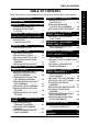
TABLE OF CONTENTS TABLE OF CONTENTS NOTE: The procedures in this manual pertain to all five (5) scooter models EXCEPT where specified. WARNING/SPECIAL NOTES .................. 2 PROCEDURE 7 - CONTROLLER ........... 37 REMOVING/INSTALLING CONTROLLER ................................37 REMOVING/INSTALLING CONTROLLER HARNESSES ..........39 REPLACING CIRCUIT BREAKER ......43 SPECIFICATIONS ................................... 4 PROCEDURE 1 - GENERAL GUIDELINES5 OPERATING INFORMATION ................
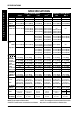
SPECIFICATIONS SPECIFICATIONS S P E C I F I C A T I O N S SX-3P LYNX (3-Wheel Models) SX-3 LX-3 PANTHER (4-Wheel Models) Plus LX-3 LX-4 MX- 4 Overall Length: 43.5-inches (104 cm) 43.5-inches (104 cm) 47-inches (119 cm) 47-inches (119 cm) 47.5-inches (125 cm) 54-inches (137 cm) Overall Width: 23-inches (58 cm) 23-inches (58 cm) Ground Clearance: 25-inches (64 cm) 25-inches (64 cm) 25-inches (64 cm) 26-inches (66 cm) 3.5-inches (8.89 cm)3.5-inches (8.89 cm) 3-inches (7.62 cm) 3-inches (7.62 cm) 3.
GENERAL GUIDELINES PROCEDURE 1 This Procedure Includes the Following: G E N E R A L Operating Information Warning/Caution Label Location OPERATING INFORMATION GENERAL WARNINGS Performance adjustments should ONLY be made by professionals of the healthcare field or persons fully conversant with this process and the driver's capabilities. Incorrect settings could cause injury to the driver, bystanders, damage to the powered scooter and surrounding property.
PROCEDURE 1 G E N E R A L G U I D E L I N E S GENERAL GUIDELINES EMI WARNINGS (CONTINUED) The sources of radiated EMI can be broadly classified into three types: 1) Hand-held Portable transceivers (transmitters-receivers with the antenna mounted directly on the transmitting unit. Examples include: citizens band (CB) radios, "walkie talkie," security, fire, and police transceivers, cellular telephones, and other personal communication devices.
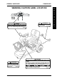
GENERAL GUIDELINES PROCEDURE 1 WARNING/CAUTION LABEL LOCATION DELTA TILLER ! ! WARNING Remove key from the ignition while scooter is not in use. Otherwise, injury and/or damage to the scooter or surrounding property may occur. WARNING DO NOT operate without the antitip tubes installed. 60106X144 1090105 ! WARNING DO NOT operate the scooter unless the tiller is in the locked position. ! CAUTION DO NOT lift scooter up by the front or rear shroud. Otherwise, damage to the scooter may occur.
PROCEDURE 2 S A F E T Y I N S P E C T I O N M A I N T E N A N C E SAFETY INSPECTION/MAINTENANCE/TROUBLESHOOTING This Procedure Includes the Following: Safety Inspection Checklist Maintenance NOTE: Every six (6) months take the scooter to a qualified dealer for a thorough inspection and servicing. Regular cleaning will reveal loose or worn parts and enhance the smooth operation of the scooter. To operate properly and safely, the scooter must be cared for just like any other vehicle.
SAFETY INSPECTION/MAINTENANCE/TROUBLESHOOTING MAINTENANCE PROCEDURE 2 CAUTION Ensure that the cover is removed from the grease nipple BEFORE operation of the PANTHER MX-4 scooter. Otherwise, damage to the scooter may occur. WARNING After ANY adjustments, repair or service and BEFORE use, make sure that all attaching hardware is tightened securely - otherwise, injury or damage may occur. 4.
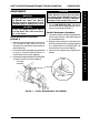
PROCEDURE 2 S A F E T Y SAFETY INSPECTION/MAINTENANCE/TROUBLESHOOTING Lubrication Points (FIGURE 2) 1. Every six (6) months the following components ® should be lubricated. Use a Teflon lubricant. (FIGURE 2). A. Seat Lever, Connecting Pin, and Release Pin. B. Axle of Scooter. I N S P E C T I O N 2. For all Models EXCEPT the PANTHER MX - 4: A. Remove the four (4) bolts securing the gearbox cover to the transaxle and remove the gearbox cover. C. Top of Seat Adaptor. B.
SEAT PROCEDURE 3 4. While holding the swivel release lever in the upward position, insert the NEW seat post into the seat frame. This Procedure Includes the Following: Replacing Seat Post NOTE: The seat post locks at 90° intervals. In order to ensure that the NEW seat post is locked into position, it may be necessary to rotate the seat post until an audible “click” is heard.
PROCEDURE 4 TILLER 3. Repeat this procedure for the other pointed locking tab of the LED canopy. This Procedure Includes the Following: Replacing Hand Grips 4. Remove the EXISTING LED canopy and the EXISTING rubber gasket. Replacing LED Canopy Replacing Throttle Lever T I L L E R 5. Discard the EXISTING LED canopy and the EXISTING rubber gasket.
TILLER PROCEDURE 4 NOTE: To ensure the NEW throttle lever performs correctly, make certain the tab on the back of the NEW throttle lever is positioned between the two (2) ends of the spring on the potentiometer assembly. (DETAIL “A”) REMOVING/INSTALLING TILLER ASSEMBLY 5. Position the NEW throttle lever on the potentiometer assembly. Ensure that tiller is properly adjusted before driving the scooter. Refer to TILLER ADJUSTMENT in PROCEDURE 8 of the Owner’s Manual, part number 1090132. WARNING 6.
PROCEDURE 4 TILLER Section A - Disassembling/Assembling Scooter (FIGURE 4) T I L L E R DISASSEMBLING. 1. If necessary, remove the floor basket. Refer to REMOVING/INSTALLING THE FLOOR BASKET in PROCEDURE 11 of the Owner’s Manual, part number 1090132. 2. Remove the batteries. Refer to REMOVING/INSTALLING THE BATTERIES WITH CABLES in PROCEDURE 4 of the Owners Manual, part number 1090132. 3. If necessary, remove the on - board battery charger.
TILLER PROCEDURE 4 9. For PANTHER MX - 4, remove the brake cable from the retaining tabs on the underside of the front frame assembly. 10. Refer to the chart on page 11 of this manual to determine which section(s) need to be performed next to successfully complete the removal/installation of the tiller assembly. ASSEMBLING. 1. Secure the tiller wiring harness in the retaining tabs on the underside of the front frame assembly. 2.
PROCEDURE 4 TILLER Section C - Disconnecting/Connecting Head light Assembly (FIGURE 6) DISCONNECTING. 1. For LYNX LX - 3 ONLY - slowly pull the head light assembly away from the base handle bar joint. T I L L E R 2. Pull back the plastic guards on the RED and BLACK cables connecting the tiller wiring harness to the head light assembly. 3. Disconnect the RED and BLACK cable metal connectors of the head light assembly from the RED and BLACK cable metal connectors of the tiller wiring harness. 4.
TILLER PROCEDURE 4 CONNECTING (FIGURE 6). 1. Connect the RED cable metal connector of the head light assembly to the RED cable metal connector of the tiller wiring harness. 3. Push any remaining slack in the tiller wiring harness through the hole in the shroud, until the wiring harness is on the underside of the front frame assembly (DETAIL “A”). 2. Connect the BLACK cable metal connector of the head light assembly to the BLACK cable metal connector of the tiller wiring harness. 4.
PROCEDURE 4 T I L L E R TILLER Section E - Disconnecting/Connecting Base Handle Bar Joint From/To Front Frame Assembly (FIGURE 7) Section F - Removing/Installing Tiller From/To Front Frame Assembly (FIGURE 8) DISCONNECTING. 1. Remove the two (2) bolts and self-locking nuts securing the base handle bar joint (and for the LYNX LX - 3 ONLY, the head light assembly) to the front frame assembly. REMOVING. 1.
TILLER PROCEDURE 4 DETAIL “A” REMOVING/INSTALLING BOOT (FIGURE 9) Tiller Wiring Harness Hole Shroud Assembly Removing 1. Remove the tiller assembly. Refer to REMOVING/INSTALLING TILLER ASSEMBLY in this procedure of this manual. 2. Remove the EXISTING boot by sliding it over the front fork with bearing assembly. Installing 1. Install the NEW boot by sliding it over the front fork with bearing assembly. DETAIL “B” Base Handle Bar Joint 2. Install the tiller assembly.
PROCEDURE 5 S H R O U D / F O R K / W H E E L S SHROUD/FORK/WHEELS/TIE RODS B. PANTHER LX - 4: This Procedure Includes the Following: 1. Remove the front head light assembly. Refer to REMOVING/INSTALLING FRONT HEAD LIGHT ASSEMBLY in PROCEDURE 10 of this manual. Replacing Tire And Tube Removing/Installing Front Shroud Assembly / T I E R O D S Removing/Installing Fork With Bearing Assembly C. PANTHER MX - 4: Removing/Installing Front Axle Assembly 1. Remove the front head light assembly.
SHROUD/FORK/WHEELS/TIE RODS PROCEDURE 5 5. Perform one (1) of the following: C. PANTHER MX - 4: A. LYNX SX - 3, LYNX SX - 3P, LYNX LX - 3 and PANTHER LX - 4 : 1. Reinstall the front head light assembly. Refer to REMOVING/INSTALLING THE FRONT HEAD LIGHT ASSEMBLY in PROCEDURE 11 of this manual. 1. Proceed to STEP 5. B. PANTHER LX - 4: 1. Reinstall the front head light assembly. Refer to REMOVING/INSTALLING THE FRONT HEAD LIGHT ASSEMBLY in PROCEDURE 10 of this manual. 6. Reinstall the boot.
PROCEDURE 5 S H R O U D / F O R K / W H E E L S SHROUD/FORK/WHEELS/TIE RODS 4. Secure the TOP bearing bushing by threading it into the TOP bearing housing. Torque the TOP bearing bushing between 26 - 39 in./lbs. REMOVING/INSTALLING FORK WITH BEARING ASSEMBLY (FIGURE 2) / T I E R O D S CAUTION NOTE: This procedure applies to the LYNX SX - 3, LYNX SX - 3P and the LYNX LX - 3 ONLY. DO NOT overtighten the bearing gap nut. Otherwise, damage to the front fork assembly may occur. Removing 1.
SHROUD/FORK/WHEELS/TIE RODS REMOVING/INSTALLING FRONT AXLE ASSEMBLY NOTE: This procedure applies to the PANTHER LX - 4 and the PANTHER MX - 4 ONLY. PROCEDURE 5 2. Secure the front axle assembly to the front frame using the washer and self-locking nut. Torque the locking nut between 108 - 135 in./lbs. 3. Position the EXISTING washer and the right front wheel axle assembly on the front axle assembly. Panther LX - 4 (FIGURE 3) CAUTION REMOVING. 1. Remove the tiller assembly.
PROCEDURE 5 S H R O U D / F O R K / W H E E L S SHROUD/FORK/WHEELS/TIE RODS Panther MX - 4 (FIGURE 4) / T I E R O D S CAUTION REMOVING. 1. Remove the tiller assembly. Refer to REMOVING/INSTALLING TILLER ASSEMBLY in PROCEDURE 4 of this manual. DO NOT overtighten the self-locking nut securing the tie rod assembly to the right front axle. Otherwise, damage to the tie rod assembly may occur. 2. Remove the front shroud assembly.
SHROUD/FORK/WHEELS/TIE RODS PROCEDURE 5 REPLACING TIE ROD ASSEMBLY NOTE: This procedure applies to the PANTHER LX - 4 and the PANTHER MX - 4 ONLY. Panther LX - 4 (FIGURE 5) 1. Remove the tiller assembly. Refer to REMOVING/INSTALLING TILLER ASSEMBLY in PROCEDURE 4 of this manual. 2. Remove the shroud assembly. Refer to REMOVING/INSTALLING SHROUD ASSEMBLY in PROCEDURE 5 of this manual. 3. Remove the front wheels.
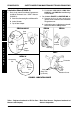
PROCEDURE 5 S H R O U D / F O R K / W H E E L S SHROUD/FORK/WHEELS/TIE RODS Bearing Gap Nut (STEPS 8 and 18) Hex Cap Screws (STEPS 6 and 20) Top Bearing Bushing (STEPS 9 and 17) / T I E R O D S Top Bearing (STEPS 10 and 16) Top Bearing Housing (STEPS 12 and 13) Steering Shaft (STEPS 11 and 15) Front Frame Assembly U - Plate (STEPS 7 and 19) Self-locking nuts (STEPS 6 and 20) Bottom Bearing Housing (STEPS 12 and 13) Bottom Bearing (STEPS 11 and 14) Tie Rod Assembly (STEPS 7 and 20) Bottom Bearing
SHROUD/FORK/WHEELS/TIE RODS PROCEDURE 5 19. Secure the NEW tie rod assembly onto the right front axle using the NEW washer and self-locking nut. Torque the NEW self-locking nut between 139 - 165 in./lbs. 20. Repeat STEPS 17-18 to attach the NEW tie rod assembly to the left front axle. 21. Secure the NEW TOP and BOTTOM bearing housing onto the front frame assembly. 22. Slide the NEW BOTTOM bearing and the NEW BOTTOM bushing onto the steering shaft.
PROCEDURE 5 S H R O U D / F O R K / W H E E L S SHROUD/FORK/WHEELS/TIE RODS REMOVING/INSTALLING SMALL TIE RODS / T I E R O D S CAUTION NOTE: This procedure applies to the PANTHER LX - 4 and the PANTHER MX - 4 ONLY. Panther LX - 4 (FIGURE 7) REMOVING. 1. Remove the tiller assembly. Refer to REMOVING/INSTALLING TILLER ASSEMBLY in PROCEDURE 4 of this manual. DO NOT overtighten the self-locking nuts securing the small tie rod to the right front wheel axle. Otherwise, damage to the tie rod may occur. 4.
SHROUD/FORK/WHEELS/TIE RODS PROCEDURE 5 Panther MX - 4 (FIGURE 8) REMOVING. 1. Remove the tiller assembly. Refer to REMOVING/INSTALLING TILLER ASSEMBLY in PROCEDURE 4 of this manual. 4. Align the mounting hole in the small tie rod with the mounting hole in the steering shaft. 5. Position the small spacer between the small tie rod and the steering shaft. CAUTION DO NOT overtighten the self-locking nuts securing the small tie rod to the the steering shaft. Otherwise, damage to the tie rod may occur. 2.
PROCEDURE 5 S H R O U D / F O R K / W H E E L S SHROUD/FORK/WHEELS/TIE RODS 3. Position the mounting bolt on the large tie rod in the mounting hole in the right front wheel axle. REMOVING/INSTALLING LARGE TIE RODS / T I E R O D S CAUTION NOTE: This procedure applies to the PANTHER LX - 4 and the PANTHER MX - 4 ONLY. DO NOT overtighten the self-locking nuts securing the large tie rod to the right front wheel axle. Otherwise, damage to the tie rod may occur. Panther LX - 4 (FIGURE 9) REMOVING. 1.
SHROUD/FORK/WHEELS/TIE RODS PROCEDURE 5 Panther MX - 4 (FIGURE 10) REMOVING. 1. Remove the tiller assembly. Refer to REMOVING/INSTALLING TILLER ASSEMBLY in PROCEDURE 4 of this manual. 4. Position the EXISTING spacer between the tie rod and the left front wheel axle. 5. Align the mounting hole in the large tie rod with the mounting hole in the left front wheel axle. CAUTION 2. Remove the front shroud assembly. Refer to REMOVING/INSTALLING FRONT SHROUD ASSEMBLY in PROCEDURE 5 of this manual. 3.
PROCEDURE 6 T R A N S A X L E / M O T O R / B R A K E TRANSAXLE/MOTOR/BRAKE 9. Remove the two (2) bolts, washers, spring washers and self-locking nuts securing the bracket and rubber spacer located near the transaxle housing to the rear frame assembly. This Procedure Includes the Following: Removing/InstallingTransaxle Assembly Replacing Motor/Brake Assembly Replacing Brake Release Lever Assembly 10. Remove the bracket and rubber spacer located near the transaxle housing. WARNING 11.
TRANSAXLE/MOTOR/BRAKE PROCEDURE 6 8. Reinstall the rear wheels. Refer to REMOVING/INSTALLING THE REAR WHEELS in PROCEDURE 9 of the Owner’s Manual, part number 1090132. 10. Reinstall the rear shroud. Refer to REMOVING/INSTALLING THE REAR SHROUD in PROCEDURE 9 of the Owner’s Manual, part number 1090132. 9. Reinstall the batteries. Refer to REMOVING/INSTALLING THE BATTERIES WITH CABLES in PROCEDURE 4 of the Owners Manual, part number 1090132. 11. Reinstall the seat.
PROCEDURE 6 T R A N S A X L E / M O T O R / B R A K E TRANSAXLE/MOTOR/BRAKE Panther MX - 4 (FIGURE 2) CAUTION REMOVING. 1. Remove the seat. Refer to REMOVING/INSTALLING THE SEAT in PROCEDURE 5 of the Owner’s Manual, part number 1090132. DO NOT overtighten the two (2) screws securing the bracket and rubber spacer to the rear frame assembly. Otherwise, damage to the bracket and rubber spacer may occur. 2. Remove the rear shroud.
TRANSAXLE/MOTOR/BRAKE PROCEDURE 6 15. Reinstall the seat. Refer to REMOVING/INSTALLING THE SEAT in PROCEDURE 5 of the Owner’s Manual, part number 1090132. REPLACING MOTOR/BRAKE ASSEMBLY (FIGURE 3) 1 Top Bolt Remove the transaxle assembly. Refer to REMOVING/INSTALLING TRANSAXLE ASSEMBLY in PROCEDURE 6 of this manual. 2. Remove the four EXISTING (4) nylock socket bolts that secure the motor/brake assembly to the transaxle assembly. Rear Shock Absorbers 3.
PROCEDURE 6 T R A N S A X L E / M O T O R / B R A K E TRANSAXLE/MOTOR/BRAKE 3. Remove the socket screw and the bolt socket securing the brake release lever to motor/brake assembly. REPLACING BRAKE RELEASE LEVER ASSEMBLY (FIGURE 4) For All Models EXCEPT Panther MX - 4 4. Remove the brake release lever. 1. Remove the seat. Refer to REMOVING/INSTALLING THE SEAT in PROCEDURE 5 of the Owner’s Manual, part number 1090132. 5.
CONTROLLER PROCEDURE 7 CONNECTING. 1. Connect the following (FIGURE 1): This Procedure Includes the Following: Removing/Installing Controller A. The RED and WHITE connectors to the slot marked “B+” on the controller. Removing/Installing Controller Harnesses Replacing Circuit Breaker B. The BLACK and GREEN connectors to the slot marked “B-” on the controller. WARNING C. The BLACK connector to the slot marked “M+” on the controller.
PROCEDURE 7 CONTROLLER 2. Reinstall the transaxle assembly. Refer to REMOVING/INSTALLING TRANSAXLE ASSEMBLY in the PROCEDURE 6 of this manual. C O N T R O L L E R INSTALLING. 1. Perform one of the following: A. LYNX SX - 3 and LYNX SX - 3P (FIGURE 2): 3. Reinstall the rear shroud. Refer to REMOVING/INSTALLING THE REAR SHROUD in PROCEDURE 5 of the Owner’s Manual, part number 1090132. 1.
CONTROLLER PROCEDURE 7 REMOVING/INSTALLING CONTROLLER HARNESSES LYNX SX - 3P AND LYNX SX - 3 Short Screws Washer Controller Washer Lynx SX - 3P And Lynx SX - 3 (FIGURE 3) REMOVING. 1. Disconnect the controller wires. Refer to DISCONNECTING/CONNECTING CONTROLLER WIRES in this procedure of the manual.
PROCEDURE 7 C O N T R O L L E R CONTROLLER 5. Connect the RED and BLACK connectors of the power wiring harnesses to the RED and BLACK connectors of the controller wiring harnesses. 8. Connect the BLUE connector of the tiller wiring harness to the BLUE connector of the controller wiring harness. 6. Connect the WHITE connector of the transaxle assembly wiring harness to the WHITE connector of the controller wiring harness. 9.
CONTROLLER PROCEDURE 7 7. Cut the cable tie securing the transaxle wiring harness to the rear frame. 8. Cut the cable tie securing the power wiring harnesses to the rear frame. 9. Remove the tiller wiring harness from the retaining tab. 5. Connect the WHITE connector of the transaxle assembly wiring harness to the WHITE connector of the controller wiring harness. NOTE: Be sure the metal connectors are in the positions noted in STEP 2 of REMOVAL. 10. Remove the wiring harnesses from the scooter. 6.
PROCEDURE 7 CONTROLLER Panther MX - 4 (FIGURE 5) C O N T R O L L E R REMOVING. 1. Disconnect the controller wires. Refer to DISCONNECTING/CONNECTING CONTROLLER WIRES in this procedure of the manual. 2. Disconnect he RED and BLACK connectors of the power wiring harnesses from the RED and BLACK connectors of the controller wiring harnesses. 3. Disconnect the WHITE connector of the transaxle assembly wiring harness from the WHITE connector of the controller wiring harness.
CONTROLLER PROCEDURE 7 8. Connect the metal connectors of the power wiring harnesses to the metal connectors of the circuit breaker. 10. Reinstall the rear shroud. Refer to REMOVING/INSTALLING THE REAR SHROUD in PROCEDURE 9 of the Owner’s Manual, part number 1090132. 9. Connect the WHITE connector of the tiller wiring harness to the WHITE connector of the controller wiring harness 11. Reinstall the seat. Refer to REMOVING/INSTALLING THE SEAT in PROCEDURE 5 of the Owner’s Manual, part number 1090132.
PROCEDURE 8 R E P L A C E M E N T P A R T S REPLACEMENT PARTS - LYNX SX - 3P Mounting Holes This Procedure Includes the Following: Replacing Tiller Charge Port Cover Tiller Charger Port Cover WARNING After ANY adjustments, repair or service and BEFORE use, make sure that all attaching hardware is tightened securely - otherwise injury or damage may occur. Turn Power OFF and remove key from ignition. Disconnect battery harness from the motor lead.
REPLACEMENT PARTS - LYNX LX - 3 PROCEDURE 9 This Procedure Includes the Following: Removing/Installing Head light Assembly Tiller Wiring Harness WARNING After ANY adjustments, repair or service and BEFORE use, make sure that all attaching hardware is tightened securely - otherwise injury or damage may occur. Head light Assembly Turn Power OFF and remove key from ignition. Disconnect battery harness from the motor lead.
PROCEDURE 10 R E P L A C E M E N T P A R T S REPLACEMENT PARTS - PANTHER LX - 4 5. Reposition the plastic guards over the metal connectors on the RED and BLACK cables connecting the tiller wiring harness to the head light assembly (DETAIL “A”). This Procedure Includes the Following: Removing/Installing Head Light Assembly Replacing Tiller Charge Port Cover 6. Return the front frame assembly to the upright position.
REPLACEMENT PARTS - PANTHER LX - 4 REPLACING TILLER CHARGER PORT COVER (FIGURE 2) PROCEDURE 10 5. Secure the NEW cushion to the front frame assembly using the two (2) NEW mounting screws, spring washers and washers. Securely tighten. NOTE: Save the two (2) mounting screws and selflocking nuts for reuse when installing the NEW tiller charger port cover. 1. Remove the two (2) mounting screws and selflocking nuts securing the tiller charger port cover to the tiller assembly. 2.
PROCEDURE 11 R E P L A C E M E N T P A R T S REPLACEMENT PARTS - PANTHER MX - 4 8. Remove the two (2) self-locking nuts, three (3) washers, spring washer, spring and the long screw securing the bottom of the head light assembly to the bracket on the front frame assembly. This Procedure Includes the Following: Removing/Installing Head Light Assembly Replacing Tail Light Assembly Replacing Disc Brake Assembly 9. Remove the head light assembly from the front shroud assembly.
REPLACEMENT PARTS - PANTHER MX - 4 PROCEDURE 11 13. Position the rubber spacer and the front bumper 15. Return the front frame assembly to the upright so that the mounting holes in the rubber spacer position. and the front bumper align with the mounting 16. Reassemble the front frame assembly and the holes in the front shroud assembly. rear frame assembly. Refer to TRANSPORT14.
PROCEDURE 11 R E P L A C E M E N T P A R T S REPLACEMENT PARTS - PANTHER MX - 4 Locking Tabs (Squeeze Together) REPLACING TAIL LIGHT ASSEMBLY (FIGURE 2) 1. Remove the rear shroud. Refer to REMOVING/ INSTALLING THE REAR SHROUD in PROCEDURE 9 of the Owner’s Manual, part number 1090132. Cables Rubber Spacer 2. Disconnect the tail light assembly from the tail light cable by performing STEPS 2-3 in REPLACING TAIL LIGHT CABLE in this procedure of this manual. Steel Plate 3.
REPLACEMENT PARTS - PANTHER MX - 4 Plastic Guards PROCEDURE 11 8. Secure the NEW disc brake assembly to the transaxle assembly using the four (4) NEW hex cap screws and spring washers. Torque the hex cap screws between 43 - 61 in./lbs. Tail Light Cable 9. Reconnect the hand brake cable assembly. Refer to REMOVING/INSTALLING TILLER ASSEMBLY, SECTION “B” - DISCONNECTING/ CONNECTING HAND BRAKE CABLE ASSEMBLY in PROCEDURE 4 of this manual. Metal Connectors Tail Light Assembly 10.
PROCEDURE 11 R E P L A C E M E N T P A R T S REPLACEMENT PARTS - PANTHER MX - 4 4. Disconnect the hand brake cable assembly. Refer to REMOVING/INSTALLING TILLER ASSEMBLY, SECTION “B” - DISCONNECTING/ CONNECTING HAND BRAKE CABLE ASSEMBLY in PROCEDURE 4 of this manual. 5. Remove the self-locking nut and washer securing the brake arm to the cam. NOTE: Save the spring for reuse when installing the NEW disc brake shoes. 6. Remove the spring securing the two (2) disc brake shoes to the brake disc. 7.
REPLACEMENT PARTS - PANTHER MX - 4 14. Install the NEW bolt securing the NEW hand brake assembly to the handle bar. Refer to DETAIL “A”. Securely tighten. PROCEDURE 11 REMOVING/INSTALLING FRONT SHOCK ABSORBERS (FIGURE 7) Removing Hand Brake Assembly Handle Bar 1. Separate the front frame assembly from the rear frame assembly. Refer to TRANSPORTING THE SCOOTER in PROCEDURE 10 of the Owner’s Manual, part number 1090132. Bolt 2. Remove the front wheels.
PROCEDURE 11 R E P L A C E M E N T P A R T S REPLACEMENT PARTS - PANTHER MX - 4 5. If necessary, repeat this procedure for the other front shock absorber. 6. Return the front frame assembly to the upright position. 7. Reinstall the front wheels. Refer to REMOVING/ INSTALLING THE FRONT WHEELS in PROCEDURE 9 of the Owner’s Manual, part number 1090132. Installing NOTE: When installing the bolts for the rear shock absorber, the TOP and BOTTOM bolts should be facing opposite directions. 1. 8.
REPLACEMENT PARTS - PANTHER MX - 4 Top Bolt Bottom Bolt PROCEDURE 11 R E P L A C E M E N T Rear Shock Absorber Rear Frame Assembly P A R T S FIGURE 8 - REMOVING/INSTALLING REAR SHOCK ABSORBER P A N T H E R M X 4 55
PROCEDURE 12 OPTIONS 8. While perfoming STEP 7, pull the YELLOW wire out from the back of the YELLOW or WHITE connector (depending on scooter model) of the tiller wiring harness. This Procedure Includes the Following: Preparing the Scooter for Left Hand Operation O P T I O N S WARNING 9. Repeat STEPS 5-8 for the ORANGE wire coming out of the rear of the YELLOW or WHITE connector (depending on scooter model) of the tiller wiring harness.
OPTIONS PROCEDURE 12 17. Position the NEW Forward/Reverse sticker OVER the EXISTING Forward/Reverse sticker on the control panel (DETAIL “A”). NOTE: The NEW Forward/Reverse sticker is also available as a purchase part.
NOTES NOTES N O T E S ____________________________________________________________________________ ____________________________________________________________________________ ____________________________________________________________________________ ____________________________________________________________________________ ____________________________________________________________________________ ____________________________________________________________________________ _________________________
WARRANTY LIMITED WARRANTY PLEASE NOTE: THE WARRANTY BELOW HAS BEEN DRAFTED TO COMPLY WITH FEDERAL LAW APPLICABLE TO PRODUCTS MANUFACTURED AFTER JULY 4, 1975. This warranty is extended only to the original purchaser/user of our products. This warranty gives you specific legal rights and you may also have other legal rights which vary from state to state.
Invacare Corporation www.invacare.com USA Canada One Invacare Way Elyria, Ohio USA 44036-2125 800-333-6900 5970 Chedworth Way Mississauga, Ontario L5R 3T9, Canada 905-890-8838 Invacare is a registered trademark of Invacare Corporation. © 1999 Invacare Corporation Form No. 99-188 Part No.