Owner's Operator and Maintenance Manual POWER TILT ONLY FOR PRONTO M71 AND M91 POWER WHEELCHAIRS DEALER: THIS MANUAL MUST BE GIVEN TO THE USER OF THE WHEELCHAIR. USER: BEFORE USING THIS WHEELCHAIR, READ THIS MANUAL AND SAVE FOR FUTURE REFERENCE.
WARNING WARNING WARNING DO NOT OPERATE THIS EQUIPMENT WITHOUT FIRST READING AND UNDERSTANDING THIS MANUAL. IF YOU ARE UNABLE TO UNDERSTAND THE WARNINGS, CAUTIONS, AND INSTRUCTIONS, CONTACT A HEALTHCARE PROFESSIONAL, DEALER OR TECHNICAL PERSONNEL IF APPLICABLE BEFORE ATTEMPTING TO USE THIS EQUIPMENT - OTHERWISE INJURY OR DAMAGE MAY RESULT. THE INITIAL SET UP OF THIS WHEELCHAIR MUST BE PERFORMED BY A QUALIFIED TECHNICIAN.
TABLE OF CONTENTS TABLE OF CONTENTS LABEL LOCATIONS .......................................................................... 5 SPECIFICATIONS ............................................................................. 6 PROCEDURE 1 - GENERAL GUIDELINES ........................................... 7 Safety/Handling Of Wheelchairs ........................................................................................................... 13 PROCEDURE 2 - SAFETY INSPECTION/TROUBLE SHOOTING ...........
SPECIAL NOTES SPECIAL NOTES SPECIAL NOTES WARNING/CAUTION notices as used in this manual apply to hazards or unsafe practices which could result in personal injury or property damage. NOTICE THE INFORMATION CONTAINED IN THIS DOCUMENT IS SUBJECT TO CHANGE WITHOUT NOTICE. As a manufacturer of wheelchairs, Invacare endeavors to supply a wide variety of wheelchairs to meet many needs of the end user.
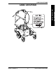
LABLE LOCATIONS LABEL LOCATIONS 5 Power Tilt Only For M71 and M91. SPECIAL NOTES LABLE LOCATIONS Part No.
SPECIFICATIONS SPECIFICATIONS SPECIFICATIONS NOTE: Refer to the wheelchair owner's manual for complete specifications on base and operation.
GENERAL GUIDELINES SECTION 1 This Procedure Includes the Following: Controller Settings/Repair or Service Information Safety/Handling of Wheelchairs Label Location CONTROLLER SETTINGS/REPAIR OR SERVICE WARNING Set-up of the Electronic Control Unit is to be performed ONLY by a qualified technician. The final tuning adjustments of the controller may affect other activities of the wheelchair. Reprogramming the controller reduces the stability/controllability of the wheelchair.
SECTION 1 GENERAL GUIDELINES GENERAL GUIDELINES GENERAL WARNINGS DO NOT lean over the top of the back upholstery to reach objects from behind as this may cause the seating system/wheelchair to tip over. DO NOT operate the seating system while on an incline. DO NOT operate the seating system while the wheelchair is moving. NEVER operate the wheelchair while in any tilted position over 20o RELATIVE TO THE VERTICAL POSITION.
GENERAL GUIDELINES SECTION 1 DO NOT stand on the frame of the seating system/wheelchair. Anti-tippers MUST BE attached at all times. DO NOT use the footplates as a platform. When getting in or out of the seating system/wheelchair, make sure that the footplates are in the upward position or swing footrests towards the outside of the seating system/ wheelchair. ALWAYS wear your seat positioning strap.
GENERAL GUIDELINES SECTION 1 GENERAL GUIDELINES WEIGHT TRAINING Invacare DOES NOT recommend the use of its wheelchairs as a weight training apparatus. Invacare wheelchairs have NOT been designed or tested as a seat for any kind of weight training. If occupant uses said wheelchair as a weight training apparatus, INVACARE SHALL NOT BE LIABLE FOR BODILY INJURY AND THE WARRANTY IS VOID. WEIGHT LIMITATION The power tilt only weight limit is 250 lbs. reguardless of wheelchair weight limit.
GENERAL GUIDELINES SECTION 1 ELECTROMAGNETIC INTERFERENCE (EMI) The sources of radiated EMI can be broadly classified into three types: Hand-held Portable transceivers (transmitters-receivers with the antenna mounted directly on the transmitting unit. Examples include: citizens band (CB) radios, "walkie talkie," security, fire, And police transceivers, cellular telephones, and other personal communication devices.
GENERAL GUIDELINES SECTION 1 GENERAL GUIDELINES POWERED WHEELCHAIR ELECTROMAGNETIC INTERFERENCE (EMI) Because EM energy rapidly becomes more intense as one moves closer to the transmitting antenna (source), the EM fields from hand-held radio wave sources (transceivers) are of special concern. It is possible to unintentionally bring high levels of EM energy very close to the powered wheelchair's control system while using these devices. This can affect powered wheelchair movement and braking.
GENERAL GUIDELINES SECTION 1 SAFETY/HANDLING OF WHEELCHAIRS Use this information only as a basic guide. The techniques that are discussed on the following pages have been used successfully by many. Individual wheelchair users often develop skills to deal with daily living activities that may differ from those described in this manual.
SECTION 1 GENERAL GUIDELINES GENERAL GUIDELINES A NOTE TO WHEELCHAIR ASSISTANTS When assistance to the wheelchair user is required, remember to use good body mechanics. Keep your back straight and bend your knees whenever tilting wheelchair or traversing curbs, or other impediments. Also, be aware of detachable parts such as arms or the footboard.
GENERAL GUIDELINES SECTION 1 TRANSFERRING TO AND FROM OTHER SEATS WARNING CAUTION When transferring, position yourself as far back as possible in the seat. This will prevent broken screws, damaged upholstery and the possibility of the wheelchair tipping forward. NOTE: This activity may be performed independently provided you have adequate mobility and upper body strength. 1.
SECTION 1 GENERAL GUIDELINES GENERAL GUIDELINES REACHING, LEANING, BENDING AND BENDING - FORWARD Position the front AND rear casters so that they are extended as far rearward as possible and engage Motor Release Levers. WARNING DO NOT attempt to reach objects if you have to move forward in the seat or pick them up from the floor by reaching down between your knees. REACHING, BENDING - BACKWARD WARNING DO NOT lean over the top of the back upholstery.
PROCEDURE 2 SAFETY INSPECTION/TROUBLESHOOTING This Procedure Includes the Following: Safety Inspection Checklist SAFETY INSPECTION CHECKLIST Initial adjustments should be made to suit your personal body structure and preference. Thereafter follow these maintenance procedures. NOTE: Refer to the wheelchair owner's manual for a complete safety inspection checklist on the base. ITEM INITIALLY INSPECT/ ADJUST MONTHLY ELECTRICAL CONNECTIONS l Make sure all electrical connections are secure.
SAFETY INSPECTION/TROUBLESHOOTING SECTION 2 NOTE: Refer to the wheelchair owner's manual for complete mechanical and electrical troubleshooting guides on the base. NOTE: Refer to the individual CONTROLLER MANUAL supplied with each wheelchair for additional troubleshooting information and explanation of error codes. SYMPTOM PROBABLE CAUSE SOLUTIONS Wheelchair Power ON but does not drive. System tilted beyond drive lockout angle. Tilt to neutral (upright) position. Contact Dealer/ Invacare for Service.
SEAT ASSEMBLY SECTION 3 This Procedure Includes the Following: Operating The Power Tilt Only Tilting The Seat Assembly WARNING NEVER operate the wheelchair while in any tilted position over 20o RELATIVE TO THE VERTICAL POSITION. If the drive lock-out does not stop the wheelchair from operating in a tilt position 20o RELATIVE TO THE VERTICAL POSITION, DO NOT operate the wheelchair. Have the wheelchair serviced by a dealer or qualified technician.
SECTION 3 SEAT ASSEMBLY SEAT ASSEMBLY TILTING THE SEAT ASSEMBLY (FIGURE 2) NOTE: Removing the seat is not necessary to access to the battery compartment on wheelchairs equipped with a power tilt only seating system. The seat assembly with power tilt only tilts back and propped in place to provide access to the batteries and underside of the seat. WARNING Make sure power to the wheelchair is OFF before performing this procedure.
SEAT ASSEMBLY SECTION 3 DETAIL "A" Detent Pin Power Tilt Only Frame SEAT ASSEMBLY Front Seat Posts DETAIL "B" Clip Seat Assembly (Front Edge) Detent Pin UP/OPEN POSITION Detent Pin DOWN/CLOSED POSITION Power Tilt Only Frame Prop Rod Bracket FIGURE 2 - TILTING THE SEAT ASSEMBLY Part No. 1118362 Rev A 21 Power Tilt Only For M71 and M91.
SECTION 4 SEAT ASSEMBLY This Procedure Includes the Following: SEAT ASSEMBLY Charging Batteries CHARGING BATTERIES WARNING NEVER attempt to recharge the batteries by attaching cables directly to the battery terminals. DO NOT attempt to recharge the batteries and operate the wheelchair at the same time. DO NOT attempt to recharge the batteries when the wheelchair has been exposed to ANY type of moisture. DO NOT attempt to recharge the batteries when the wheelchair is outside.
SEAT ASSEMBLY SECTION 4 CHARGING USING AN INDEPENDENT CHARGER (FIGURE 1) NOTE: The charger port located on the FRONT of the joystick requires the use of an independent charger. CAUTION DO NOT use an independent charger rated for over 8 amps. Otherwise, damage may occur. Required Items: MODEL M91 and M71 Battery Charger * Power Cord Supplied Supplied * NOTE: AC power cord (3-prong plug, 15 ampere current rating; industrial type) 1. Perform one of the following: A.
SECTION 5 ADJUSTING SEAT ASSEMBLY This Procedure Includes the Following: Adjusting The Seat Height SEAT ASSEMBLY Adjusting The Seat Position ADJUSTING THE SEAT HEIGHT (FIGURE 1) NOTE: The M91 seat assembly can be adjusted to three (3) height positions in 1/2-inch increments. NOTE: The M71 seat assembly can be adjusted to five (5) height positions in 1/2-inch increments. WARNING DO NOT attempt to adjust the seat height. This procedure MUST be performed by a qualified technician.
ADLUSTING SEAT ASSEMBLY SECTION 5 M71 FRAME SEAT TO FLOOR HEIGHT 20-1/2-inches 5 20-inches 4 19-1/2-inches 3 19-inches 2 18-1/2-inches 1 MOUNTING HOLE 1 2 3 4 5 Front Seat Post Locknut Support Tube Mounting Screw M91 FRAME SEAT TO FLOOR HEIGHT Rear Seat Support Assembly MOUNTING HOLE 1 2 3 MOUNTING HOLE 1 2 3 4 5 M91 MOUNTING HOLE 21-inches 3 20-1/2-inches 2 20-inches 1 MOUNTING HOLE 1 2 3 Mounting Screw Support Tube Front Seat Post Locknut FIGURE 6 - ADJUSTING THE SEAT HEIGH
SECTION 5 ADJUSTING SEAT ASSEMBLY ADJUSTING THE SEAT POSITION (FIGURE 2) SEAT ASSEMBLY NOTE: The seat can be adjusted to three (3) positions in 1/2-inch increments. WARNING DO NOT attempt to adjust the seat depth. This procedure MUST be performed by a qualified technician. Invacare recommends using a assistant when preforming this procedure otherwise injury or damage may result. 1.
ADLUSTING SEAT ASSEMBLY SECTION 5 M91 SEAT ADJUSTMENT POSITIONS SEAT TO FLOOR HEIGHT M91 SEAT POSITION REAR MIDDLE FORWARD OK OK OK 20-1/2-inches OK OK OK As shipped with 20 and 22-inch Deep Seat As shipped with 18-inch Deep Seat As shipped with 16-inch Deep Seat 20-inches M71 SEAT ADJUSTMENT POSITIONS SEAT TO FLOOR HEIGHT M71 SEAT POSITION REAR MIDDLE FORWARD 20-1/2-inches OK OK NO 20-inches OK OK NO 19-1/2-inches OK OK NO 19-inches OK OK NO As shipped with 20-inch Deep
LIMITED WARRANTY PLEASE NOTE: THE WARRANTY BELOW HAS BEEN DRAFTED TO COMPLY WITH FEDERAL LAW APPLICABLE TO PRODUCTS MANUFACTURED AFTER JULY 4, 1975. This warranty is extended only to the original purchaser/user of our products. This warranty gives you specific legal rights and you may also have other legal rights which vary from state to state.