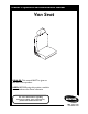
Owner’s Operator and Maintenance Manual Van Seat DEALER: This manual MUST be given to the user of the product. USER: BEFORE using this product, read this manual and save for future reference. For more information regarding Invacare products, parts, and services, please visit www.invacare.
REFERENCE DOCUMENTS WARNING A qualified technician MUST perform the initial set up of this wheelchair. Also, a qualified technician MUST perform all procedures in the service manual. DO NOT use this product or any available optional equipment without first completely reading and understanding these instructions and any additional instructional material such as owner’s manuals, service manuals or instruction sheets supplied with this product or optional equipment.
TABLE OF CONTENTS TABLE OF CONTENTS REFERENCE DOCUMENTS ................................................................. 2 REGISTER YOUR PRODUCT ............................................................... 4 SPECIAL NOTES ................................................................................ 5 LABEL LOCATIONS ........................................................................... 6 TYPICAL PRODUCT PARAMETERS ....................................................
TABLE OF CONTENTS TABLE OF CONTENTS Replacing Heel Loops ..............................................................................................................................19 Raising/Lowering Elevating Front Riggings ..........................................................................................19 Adjusting/Replacing Telescoping Front Rigging Supports................................................................20 Removing/Installing the Center Mount Footrest .......................
SPECIAL NOTES SPECIAL NOTES Signal words are used in this manual and apply to hazards or unsafe practices which could result in personal injury or property damage. Refer to the table below for definitions of the signal words. SIGNAL WORD MEANING DANGER Danger indicates an imminently hazardous situation which, if not avoided, will result in death or serious injury. WARNING Warning indicates a potentially hazardous situation which, if not avoided, could result in death or serious injury.
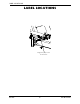
LABEL LOCATIONS LABEL LOCATIONS Weight Capacity Label located here Van Seat 6 Part No 1143195
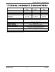
TYPICAL PRODUCT PARAMETERS TYPICAL PRODUCT PARAMETERS SEAT WIDTH RANGE: SEAT DEPTH: BACK HEIGHT W/O HEADREST: BACK ANGLE RANGE SEMI-RECLINE: FULL RECLINE: 18-INCH VAN SEAT 20-INCH VAN SEAT 22-INCH VAN SEAT 18 inches 20 inches 22 inches 16 -18 inches 18-20 inches 20-22 inches 18 inches 18 inches 18 inches 35° to 115° 35° to 170° 35° to 115° 35° to 170° 35° to 115° 35° to 170° UPHOLSTERY: Grey Vinyl, Grey Cloth, Tan Vinyl SEAT-TO-FLOOR: 22½ to 23½ inches (Cushion Not Compressed) OVERALL W
SECTION 1—GENERAL GUIDELINES SECTION 1—GENERAL GUIDELINES WARNING SECTION 1 - GENERAL GUIDELINES contains important information for the safe operation and use of this product. Controller Settings/Repair or Service DO NOT service or adjust your wheelchair while occupied, unless otherwise noted. Wheelchairs should be examined during maintenance for signs of corrosion (water exposure, incontinence, etc.). Electrical components damaged by corrosion should be replaced immediately.
SECTION 1—GENERAL GUIDELINES DO NOT lean over the top of the back upholstery to reach objects behind you, as this may cause the wheelchair to tip over. ALWAYS keep hands and fingers clear of moving parts to avoid injury. DO NOT store items under seat ‐ interference with seat latch may result. DO NOT use an escalator to move a wheelchair between floors. Serious bodily injury may occur. DO NOT engage or disengage the motor release levers until the power is in the Off position.
SECTION 1—GENERAL GUIDELINES Before performing any maintenance, adjustment or service verify that On/Off switch on the joystick is in the Off position. ALWAYS wear your seat positioning strap. The seat positioning strap is a positioning belt only. It is not designed for use as a safety device withstanding high stress loads such as auto or aircraft safety belts. If signs of wear appear, belt must be replaced immediately.
SECTION 1—GENERAL GUIDELINES Accessories EXTREME care should be exercised when using oxygen in close proximity to electric circuits and other combustible materials. Contact your oxygen supplier for instruction in the use of oxygen. Rain Test Invacare has tested its power wheelchairs in accordance with ISO 7176 “Rain Test.” This provides the end user or his/her assistant sufficient time to remove his/her power wheelchair from a rain storm and retain wheelchair operation.
SECTION 2—SAFETY/HANDLING OF WHEELCHAIRS SECTION 2—SAFETY/HANDLING OF WHEELCHAIRS Refer to wheelchair base owner’s manual for complete safety/handling information. Pinch Points WARNING DO NOT store or place items under the seat. Pinch point may occur when adjusting the arm angle position. Pinch Point FIGURE 2.
SECTION 3—SAFETY INSPECTION/TROUBLESHOOTING SECTION 3—SAFETY INSPECTION/ TROUBLESHOOTING NOTE: Every six months or as necessary take your wheelchair to a qualified dealer for a thorough inspection and servicing. Regular cleaning will reveal loose or worn parts and enhance the smooth operation of your wheelchair. To operate properly and safely, your wheelchair must be cared for just like any other vehicle. Routine maintenance will extend the life and efficiency of your wheelchair.
SECTION 3—SAFETY INSPECTION/TROUBLESHOOTING Inspect/Adjust Monthly ❑ Ensure all fasteners are secure. ❑ Inspect for any loose hardware on the wheelchair. ❑ Inspect the seat positioning strap for signs of wear. Replace if worn or damaged. ❑ Ensure that the buckle on the seat positioning strap latches. Replace if necessary. ❑ Verify that the hardware that attaches the seat positioning strap to the seat frame is secure and undamaged. Replace if necessary.
SECTION 4—ARMS SECTION 4—ARMS WARNING After ANY adjustments, repair or service and before use, make sure that all attaching hardware is tightened securely - otherwise injury or damage may result. Before performing any maintenance, adjustment or service verify that On/Off switch on the joystick is in the Off position. Adjusting Armrests WARNING Pinch point may occur when adjusting the arm angle position (Detail “A”). Angle NOTE: For this procedure, refer to Detail “A” of FIGURE 4.1. 1.
SECTION 5—SEAT SECTION 5—SEAT WARNING After ANY adjustments, repair or service and before use, make sure that all attaching hardware is tightened securely - otherwise injury or damage may result. Before performing any maintenance, adjustment or service verify that On/Off switch on the joystick is in the Off position. Adjusting the Headrest Headrest NOTE: For this procedure, refer to FIGURE 5.1. 1. To raise headrest, lift headrest Up to desired position.
SECTION 6—FRONT RIGGINGS SECTION 6—FRONT RIGGINGS WARNING After ANY adjustments, repair or service and before use, make sure that all attaching hardware is tightened securely - otherwise injury or damage may result. DO NOT stand on the front riggings, otherwise damage may occur. When getting in or out of the wheelchair, make sure that the footplates on the front riggings are in the upward position or moved out of the way.
SECTION 6—FRONT RIGGINGS Removing 1. Push the front rigging release lever inward and rotate the footrest out. 2. Lift up on front rigging and remove from the wheelchair. 3. Repeat STEPS 1‐2 for opposite side of wheelchair. Adjusting Footrest Height Model PHWH93 NOTE: For this procedure, refer to FIGURE 6.2. 1. Remove any accessories from the footrest(s). 2. Remove the footrest from the wheelchair. Refer to Installing/ Removing Front Riggings on page 17.
SECTION 6—FRONT RIGGINGS 3. Securely tighten the lug bolt and locknut that secure the lower footrest to the footrest support. 4. Repeat STEPS 1‐3 for the opposite side of the wheelchair footrest, if necessary. Replacing Heel Loops NOTE: For this procedure, refer to FIGURE 6.4. 1. Note the position of hex bolt, coved washers and locknut for reinstallation. Locknut 2. Remove the hex bolt, coved washers and locknut that secure the lower footrest to the footrest support.
SECTION 6—FRONT RIGGINGS Adjusting/Replacing Telescoping Front Rigging Supports NOTE: For this procedure, refer to FIGURE 6.6 on page 21. NOTE: When adjusting the telescoping front rigging support depth, ensure the footplate does not interfere with the caster wheel rotation. NOTE: Telescoping front rigging supports may be extended up to 2‐inches from the wheelchair frame in 1‐inch increments. This adjustment does not affect seat depth.
SECTION 6—FRONT RIGGINGS Inner Mounting Holes Mounting Bolts Not Used Telescoping Front Rigging Support Seat Frame Spacer Locknuts 8 Mounting Holes 7 6 5 4 3 2 Not Used Hinge Pins STANDARD POSITION 1 INCH OUT 2 INCHES OUT 18 inches wide 20 inches wide 22 inches wide 18 inches wide 20 inches wide 22 inches wide 18 inches wide 20 inches wide 22 inches wide Holes 2 and 3 Holes 2 and 3 Holes 3 and 4 Holes 3 and 4 Holes 3 and 4 Holes 5 and 6 Holes 4 and 5 Holes 4 and 5 Holes 6 and 7
SECTION 6—FRONT RIGGINGS Removing/Installing the Center Mount Footrest NOTE: For this procedure, refer to FIGURE 6.7. Removing 1. Remove the rigging pivot pin that secures the footrest to the mounting bracket of the seat frame. 2. Hold the footrest with one hand and engage the release lever with the other while simultaneously pulling the center mount footrest out of the mounting bracket of the seat frame. Installing 1.
SECTION 6—FRONT RIGGINGS Adjusting the Height of the Center Mount Footrest WARNING While the wheelchair is moving, minimum ground clearance for the front rigging is three inches. If the wheelchair is not moving, the front rigging MUST maintain a minimum of one inch ground clearance - otherwise personal injury and damage may result. NOTE: For this procedure, refer to FIGURE 6.8. 1. Remove the two mounting screws that secure the footrest extension tube to the extension tube housing. 2.
SECTION 6—FRONT RIGGINGS Adjusting the Angle of the Manual Center Mount Footrest WARNING While the wheelchair is moving, minimum ground clearance for the front rigging is three inches. If the wheelchair is not moving, the front rigging MUST maintain a minimum of one inch ground clearance - otherwise personal injury and damage may result. NOTE: For this procedure, refer to FIGURE 6.8 on page 23 and FIGURE 6.9. 1.
SECTION 6—FRONT RIGGINGS Before 2/15/07 NOTE: For this procedure, refer to FIGURE 6.11. 1. Loosen the footplate mounting screw and move the footplate to the desired angle. Center Mount Footrest NOTE: DO NOT remove the footplate mounting screw. Footplate Footplate Mounting Screw 2. Tighten the footplate mounting screw to secure the footplate in the desired position. FIGURE 6.11 Adjusting the Footplate Angle - Before 2/15/07 3. Repeat STEPS 1 and 2 for the other footplate.
NOTES NOTES Van Seat 26 Part No 1143195
NOTES NOTES Part No 1143195 27 Van Seat
LIMITED WARRANTY PLEASE NOTE: THE WARRANTY BELOW HAS BEEN DRAFTED TO COMPLY WITH FEDERAL LAW APPLICABLE TO PRODUCTS MANUFACTURED AFTER JULY 4, 1975. This warranty is extended only to the original purchaser who purchases this product when new and unused from Invacare or a dealer. This warranty is not extended to any other person or entity and is not transferable or assignable to any subsequent purchaser or owner.