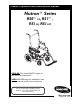
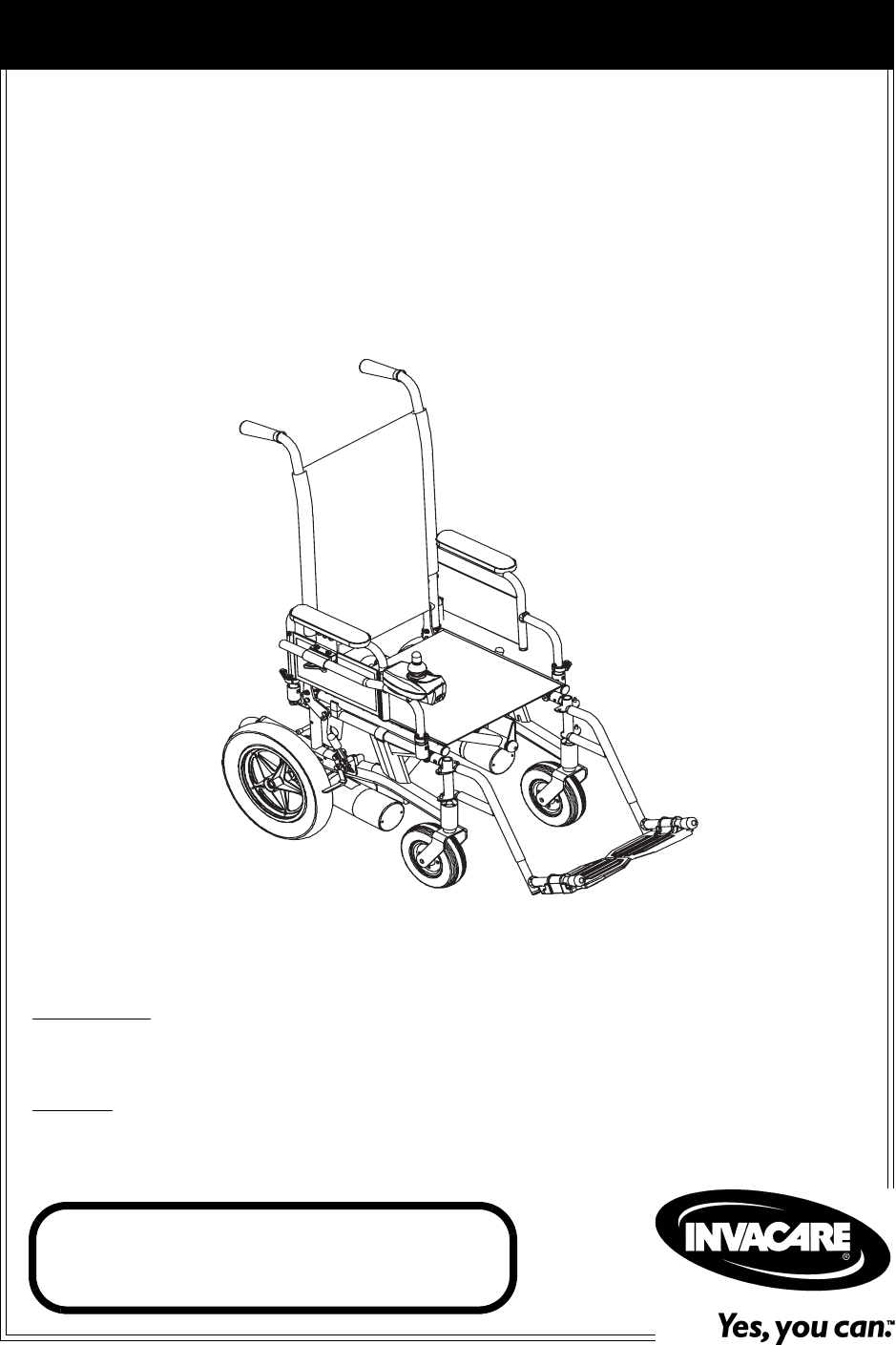
Owner’s Operator and Maintenance Manual Nutron® Series R50™LX, R51™, R51LX, R51LXP DEALER: This manual MUST be given to the user of the wheelchair. USER: BEFORE using this wheelchair, read this manual and save for future reference. For more information regarding Invacare products, parts, and services, please visit www.invacare.
WARNING A QUALIFIED TECHNICIAN MUST PERFORM THE INITIAL SET UP OF THIS WHEELCHAIR. ALSO, A QUALIFIED TECHNICIAN MUST PERFORM ALL PROCEDURES IN THE SERVICE MANUAL. WHEELCHAIR USERS: DO NOT SERVICE OR OPERATE THIS EQUIPMENT WITHOUT FIRST READING AND UNDERSTANDING (1) THE OWNER’S OPERATOR AND MAINTENANCE MANUAL AND (2) THE SEATING SYSTEM’S MANUAL (IF APPLICABLE).
TABLE OF CONTENTS TABLE OF CONTENTS REGISTER YOUR PRODUCT ............................................................... 6 SPECIAL NOTES ................................................................................ 9 TYPICAL PRODUCT PARAMETERS .................................................. 10 SECTION 1—GENERAL GUIDELINES ................................................. 11 Repair or Service Information .................................................................................................
TABLE OF CONTENTS TABLE OF CONTENTS SECTION 5—WHEELCHAIR OPERATION ........................................... 27 Operating the Wheelchair......................................................................................................................27 Turning the Power On/Off ................................................................................................................27 Using the Joystick to Drive the Chair ..........................................................................
TABLE OF CONTENTS TABLE OF CONTENTS Changing the Back Angle ........................................................................................................................41 SECTION 9—UPHOLSTERY/SEAT POSITIONING STRAP ..................... 43 Replacing Seat Upholstery......................................................................................................................43 Replacing Back Upholstery .......................................................................................
TABLE OF CONTENTS TABLE OF CONTENTS Installing/Removing the Anti-Tippers...................................................................................................69 Installing..................................................................................................................................................69 Removing ...............................................................................................................................................
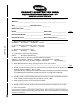
PRODUCT REGISTRATION FORM Register ONLINE at www.invacare.com - or Complete and mail this form Name _______________________________________________________________ Address _____________________________________________________________ City ___________________ State/Province __________ Zip/Postal Code ________ Email ___________________________________ Phone No. _________________ Fold here Invacare Model No. ______________________ Serial No.
Cut Along Line Fold here Fold here Invacare Product Registration Form Please Seal with Tape Before Mailing Part No.
SPECIAL NOTES SPECIAL NOTES WARNING/CAUTION notices as used in this manual apply to hazards or unsafe practices which could result in personal injury or property damage. NOTICE THE INFORMATION CONTAINED IN THIS DOCUMENT IS SUBJECT TO CHANGE WITHOUT NOTICE. WHEELCHAIR USER As a manufacturer of wheelchairs, Invacare endeavors to supply a wide variety of wheelchairs to meet many needs of the end user.
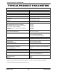
TYPICAL PRODUCT PARAMETERS TYPICAL PRODUCT PARAMETERS NUTRON R50LX, R51, R51LX, R51LXP SEAT WIDTH RANGE 14, 16, 18 or 20 inches SEAT DEPTH RANGE 16, 17 or 18 inches (17 and 18 in.
SECTION 1—GENERAL GUIDELINES SECTION 1—GENERAL GUIDELINES Repair or Service Information Set‐up of the Electronic Control Unit is to be performed ONLY by individuals certified by Invacare. The final adjustments of the controller may affect other activities of the wheelchair. Damage to the equipment could occur under these circumstances. If non‐certified individuals perform any work on these units, the warranty is void.
SECTION 1—GENERAL GUIDELINES DO NOT attempt to lift the wheelchair by lifting on any removable (detachable) parts. Lifting by means of any removable (detachable) parts of a wheelchair may result in injury to the user or damage to the wheelchair. ALWAYS wear your seat positioning strap. The seat positioning strap is a positioning belt only. It is not designed for use as a safety device withstanding high stress loads such as auto or aircraft safety belts.
SECTION 1—GENERAL GUIDELINES Grounding Instructions DO NOT, under any circumstances, cut or remove the round grounding prong from any plug used with or for Invacare products. Some devices are equipped with three‐prong (grounding) plugs for protection against possible shock hazards.
SECTION 1—GENERAL GUIDELINES Ensure the pins of the extension cord plug are the same number, size, and shape as those on the charger. DO NOT under any circumstances cut or remove the round grounding plug from the charger AC cable plug or the extension cord plug. Three (3) prong to two (2) prong adapters should not be used. Use of three (3) prong adapters can result in improper grounding and present a shock hazard to the user.
SECTION 2—EMI INFORMATION SECTION 2—EMI INFORMATION WARNING CAUTION: IT IS VERY IMPORTANT THAT YOU READ THIS INFORMATION REGARDING THE POSSIBLE EFFECTS OF ELECTROMAGNETIC INTERFERENCE ON YOUR POWERED WHEELCHAIR.
SECTION 2—EMI INFORMATION WARNING Powered Wheelchair Electromagnetic Interference (EMI) Because EM energy rapidly becomes more intense as one moves closer to the transmitting antenna (source), the EM fields from hand-held radio wave sources (transceivers) are of special concern. It is possible to unintentionally bring high levels of EM energy very close to the powered wheelchair's control system while using these devices. This can affect powered wheelchair movement and braking.
SECTION 3—SAFETY/HANDLING OF WHEELCHAIRS SECTION 3—SAFETY/HANDLING OF WHEELCHAIRS Safety/Handling of Wheelchairs “Safety and Handling” of the wheelchair requires the close attention of the wheelchair user as well as the assistant. This manual points out the most common procedures and techniques involved in the safe operation and maintenance of the wheelchair.
SECTION 3—SAFETY/HANDLING OF WHEELCHAIRS A Note to Wheelchair Assistants When assistance to the wheelchair user is required, remember to use good body mechanics. Keep your back straight and bend your knees whenever tilting wheelchair or traversing curbs, or other impediments. WARNING DO NOT attempt to lift the wheelchair by any removable (detachable) parts. Lifting by means of any removable (detachable) parts of a wheelchair may result in injury to the user or damage to the wheelchair.
SECTION 3—SAFETY/HANDLING OF WHEELCHAIRS WARNING DO NOT let the wheelchair drop the last few inches to the ground. This could result in injury to the occupant. Anti-tippers MUST BE used at all times. When outdoors on wet, soft ground or gravel surfaces, anti-tippers may not provide the same level of protection against tipover. Extra caution must be observed when traversing such surfaces. Roll the wheelchair forward and SLOWLY lower the wheelchair in one continuous movement.
SECTION 3—SAFETY/HANDLING OF WHEELCHAIRS 6. The wheelchair should not be lowered until the last stair has been negotiated and the wheelchair has been carried away from the stairway. Escalators WARNING DO NOT use an escalator to move a wheelchair between floors. Serious bodily injury may occur. Transferring To and From Other Seats WARNING ALWAYS turn the wheelchair power OFF and engage the clutches to prevent the wheels from moving BEFORE attempting to transfer in or out of the wheelchair.
SECTION 3—SAFETY/HANDLING OF WHEELCHAIRS Percentage of Weight Distribution WARNING DO NOT attempt to reach objects if you have to move forward in the seat or pick them up from the floor by reaching down between your knees. Proper positioning is essential for your safety. When reaching, leaning, bending or bending forward, it is important to use the casters as a tool to maintain stability and balance. Many activities require the wheelchair user to reach, bend and transfer in and out of the wheelchair.
SECTION 3—SAFETY/HANDLING OF WHEELCHAIRS Reaching and Bending - Backward WARNING DO NOT lean over the top of the back upholstery. This will change your center of gravity and may cause you to tip over. NOTE: For this procedure, refer to FIGURE 3.3. 1. Position wheelchair as close as possible to the desired object. 2. Point the front casters as far forward as possible to create the longest possible wheelbase. 3. Reach back only as far as your arm will extend without changing your sitting position.
SECTION 4—SAFETY INSPECTION/TROUBLESHOOTING SECTION 4—SAFETY INSPECTION/TROUBLESHOOTING NOTE: Every six (6) months or as necessary take your wheelchair to a qualified technician for a thorough inspection and servicing. Regular cleaning will reveal loose or worn parts and enhance the smooth operation of your wheelchair. To operate properly and safely, your wheelchair must be cared for just like any other vehicle. Routine maintenance will extend the life and efficiency of your wheelchair.
SECTION 4—SAFETY INSPECTION/TROUBLESHOOTING Inspect/Adjust Monthly ❑ Ensure arm pivot points are free of wear and looseness. ❑ Ensure wheel mounting bolts are secure on drive wheels. ❑ Ensure no excessive side movement or binding when drive wheels are lifted and spun when disengaged (free‐wheeling). ❑ Ensure wheel/fork assembly has proper tension when caster is spun. Caster should come to a gradual stop.
SECTION 4—SAFETY INSPECTION/TROUBLESHOOTING Troubleshooting Guide SYMPTOM Batteries draw excessive current when charging. PROBABLE CAUSE SOLUTIONS Battery failure. Have batteries checked for shorted cell. Replace if necessary. Electrical malfunction. Contact Dealer/Invacare for service. Battery failure. Check batteries for shorted cell. Replace if necessary. Malfunctioning battery charger. Contact Dealer/Invacare for service. Electrical malfunction Contact Dealer/Invacare for service.
SECTION 4—SAFETY INSPECTION/TROUBLESHOOTING Checking Battery Charge Level The following “Do’s” and “Don’ts” are provided for your convenience and safety. DON’T DO Don’t perform any installation or maintenance without first reading this manual. Read and understand this manual and any service information that accompanies a battery and charger before operating the wheelchair. Don’t perform installation or maintenance of batteries in an area that could be damaged by battery spills.
SECTION 5—WHEELCHAIR OPERATION SECTION 5—WHEELCHAIR OPERATION WARNING After ANY adjustments, repair or service and BEFORE use, make sure that all attaching hardware is tightened securely - otherwise injury or damage may result. Set-up/programming of the Electronic Control Unit is to be performed ONLY by a qualified technician. The fine tuning adjustments of the controller may affect other activities of the wheelchair. Damage to the equipment could occur under these circumstances.
SECTION 5—WHEELCHAIR OPERATION Using the Joystick to Drive the Chair NOTE: For this procedure, refer to FIGURE 5.2. The joystick is located at the front of the joystick housing and provides smooth control of speed and direction. It is equipped with 360 degrees of mobility for ease of operation. The joystick is spring‐loaded, and automatically returns to the upright (neutral) position when released. Pushing the joystick in a given direction causes the chair to move in that direction.
SECTION 5—WHEELCHAIR OPERATION SPJ™Joystick Switches and Indicators NOTE: For the following information, refer to FIGURE 5.3. Multi-Function Charger Port Located at the front of the joystick housing. This provides easy access for charging the wheelchair batteries. This port also serves as the Remote Programmer Communication connection. On/Off Toggle Switch This toggle switch is located at the back of the joystick housing.
SECTION 5—WHEELCHAIR OPERATION The Information Gauge display also serves as a system diagnostic device when a fault is detected by the control module. A specific number of flashes of the LEDs indicates the type of fault detected. Refer to the following table of the diagnostic indications of the wheelchair status. DISPLAY DESCRIPTION DEFINITION COMMENTS All three (3) LEDs are off. Power is Off. All three (3) LEDs are on. Power is On. Fewer than three (3) LEDs on implies reduced battery charge.
SECTION 6—FRONT RIGGINGS SECTION 6—FRONT RIGGINGS WARNING After ANY adjustments, repair or service and BEFORE use, make sure that all attaching hardware is tightened securely - otherwise injury or damage may result. Installing/Removing the Footrests NOTE: For this procedure, refer to FIGURE 6.1. Installing 1. Turn footrest to the side (open footplate is perpendicular to wheelchair) and position mounting holes in the footrest hinge plates with hinge pins on the wheelchair frame. 2.
SECTION 6—FRONT RIGGINGS Adjusting the Footrest Height Model PW93, PW93E, and PW93ST Footrests NOTE: For this procedure, refer to FIGURE 6.2. 1. Remove any accessory from the footrest(s). 2. Remove the footrest from the wheelchair. Refer to Installing/Removing the Footrests on page 31. NOTE: Lay footrest on a flat surface to simplify procedure. 3. Remove the hex bolt, coved washers and locknut that secure the lower footrest to the footrest support. 4. Reposition the lower footrest to the desired height. 5.
SECTION 6—FRONT RIGGINGS Model 93M, 904A, PAL4A, and PAS4A Footrests NOTE: For this procedure, refer to FIGURE 6.3. 1. Loosen, but do not remove the lug bolt and locknut that secure the lower footrest to the footrest support. 2. Reposition the lower footrest to the desired height. 3. Securely tighten the lug bolt and locknut that secure the lower footrest to the footrest support. 4. Repeat STEPS 1‐3 for the other footrest, if necessary.
SECTION 6—FRONT RIGGINGS Installing/Removing Elevating Legrests NOTE: For this procedure, refer to FIGURE 6.5. Installing 1. Turn legrest to side (open footplate is perpendicular to wheelchair) and position mounting holes in the legrest hinge plates with hinge pins on the wheelchair frame. Legrest Release Handle 2. Install the legrest hinge plates onto the hinge pins on the wheelchair frame. 3. Rotate legrest toward the inside of the wheelchair until it locks in place.
SECTION 6—FRONT RIGGINGS Adjusting Calfpads 1. Turn calfpad towards the outside of the wheelchair. 2. Slide calfpad up or down until desired position is obtained. NOTE: If one (1) of the top two (2) calfpad adjustment positions is being used, the legrest will need to be raised to avoid interference with the front stabilizers while going over obstacles or going up and down ramps. Refer to Raising/Lowering Elevating Legrests on page 34. 3. Turn the calfpad toward the inside of the wheelchair.
SECTION 6—FRONT RIGGINGS 4. Perform one (1) of the following: • Adjusting: NOTE: Telescoping front rigging supports may be extended up to 2‐inches from the wheelchair frame in 1‐inch increments. This adjustment does not effect seat depth. i. Position the telescoping front rigging support to the desired depth. • Replacing: i. Remove the existing telescoping front rigging support from the wheelchair frame. ii. Insert the new telescoping front rigging support into the wheelchair frame. iii.
SECTION 7—ARMS SECTION 7—ARMS WARNING After ANY adjustments, repair or service and BEFORE use, make sure all attaching hardware is tightened securely - otherwise injury or damage may result. Adjusting Armrest Height NOTE: For this procedure, refer to FIGURE 7.1. WARNING Make sure the height adjustment lever is in the locked position before using the wheelchair. 1. Unlock the armrest by flipping the height adjustment lever on the top front of the armrest to the up (horizontal) position. 2.
SECTION 7—ARMS Using Swing-Back Arms WARNING Make sure the armrest release lever is in the locked position before using the wheelchair. NOTE: For this procedure, refer to FIGURE 7.2. 1. Unlock the swing‐back arms by rotating the armrest release lever toward the outside of the wheelchair. 2. Pull the front of the swing‐back arm straight up/out of the arm socket and toward the rear of the wheelchair. Swing Back Arm (Front) Armrest Release Lever 3.
SECTION 7—ARMS Armrest Pad Mounting Screws Armrest Assembly Clothing Guard Mounting Screws Mounting Screws FIGURE 7.3 Replacing Desk/Full Length Armrest Pad and/or Clothing Guards (Fixed Height Arms Only) Removing/Installing Armrest WARNING Make sure the armrest release lever is in the locked position before using the wheelchair. NOTE: For this procedure, refer to FIGURE 7.4. Removing 1. Unlock the armrest by turning the armrest release levers towards the outside of the wheelchair. 2.
SECTION 8—BACK SECTION 8—BACK WARNING After ANY adjustments, repair or service and BEFORE use, make sure all attaching hardware is tightened securely - otherwise injury or damage may result. Adjusting the Back Height NOTE: For this procedure, refer to FIGURE 8.1. NOTE: Back canes must be adjusted to the same height. NOTE: Take note of the position and orientation of the back cane mounting hardware before removing.
SECTION 8—BACK Using the Fold Down Back Canes (R51, 51LX and R51LXP Models Only) WARNING The back MUST be locked securely in place before using the wheelchair. NOTE: For this procedure, refer to FIGURE 8.2. 1. Perform one (1) of the following: • Unfold ‐ Push/pull the back toward rear of wheelchair until it locks in place. • Fold ‐ Pull up on the back release latches and push the back toward the front of the wheelchair.
SECTION 8—BACK 3. Position the back angle plate to one (1) of six (6) back angles. Refer to Detail “A” of FIGURE 8.3. 4. Reinstall the front hex screw and washer, securely tighten with locknut. Refer to FIGURE 8.3 for correct hardware orientation. 5. Securely tighten the rear hex screw that secures the back adjustment plate to the wheelchair frame.
SECTION 9—UPHOLSTERY/SEAT POSITIONING STRAP SECTION 9—UPHOLSTERY/SEAT POSITIONING STRAP WARNING After ANY adjustments, repair or service and BEFORE use, make sure all attaching hardware is tightened securely - otherwise injury or damage may result. Replacing Seat Upholstery NOTE: For this procedure, refer to FIGURE 9.1. 1. Remove the eight (8) phillips screws and washers that secure the existing seat upholstery to the crossbraces. Phillips Screw Washer 2.
SECTION 9—UPHOLSTERY/SEAT POSITIONING STRAP 4. Pull the loose back canes out of the existing back upholstery. 5. Slide the loose back canes into the new back upholstery. 6. Secure the back canes to the wheelchair frame with the mounting screws and locknuts removed in STEP 1. 7. Secure the new back upholstery to the back canes with the two (2) existing upholstery mounting screws and washers. NOTE: All four (4) mounting screws and locknuts are shown. Each fold‐down back cane uses two (2) mounting screws.
SECTION 9—UPHOLSTERY/SEAT POSITIONING STRAP Rear Phillips Screw Washer Seat Upholstery Seat Positioning Strap Crossbrace FIGURE 9.3 Replacing Seat Positioning Strap Nutron® Series 45 Part No.
SECTION 10—JOYSTICK SECTION 10—JOYSTICK WARNING After ANY adjustments, repair or service and BEFORE use, make sure all attaching hardware is tightened securely - otherwise injury or damage may result. Preparing the Joystick For Use NOTE: For this procedure, refer to FIGURE 10.1. NOTE: The joystick is factory installed on the right side of the wheelchair. To reposition the joystick onto the left side of the wheelchair refer to Repositioning the Joystick on page 47.
SECTION 10—JOYSTICK Repositioning the Joystick NOTE: For this procedure, refer to FIGURE 10.2. 1. Turn the adjustment lock lever to release the joystick mounting tube from the mounting bracket. 2. Remove the joystick from the wheelchair. 3. Remove the three (3) hex screws that secure the halves (½) of the mounting bracket to the arm tube. 4. Reposition mounting bracket on opposite arm tube ensuring the threaded plate of the mounting bracket is on the inside of the arm tube as shown in FIGURE 10.2. 5.
SECTION 11—CASTERS SECTION 11—CASTERS WARNING After ANY adjustments, repair or service and BEFORE use, make sure that all attaching hardware is tightened securely - otherwise injury or damage may result. Before performing any maintenance, adjustment or service verify that ON/OFF switch on the joystick is in the OFF position. CAUTION As with any vehicle, the wheels, casters and tires should be checked periodically for cracks and wear and should be replaced.
SECTION 12—BATTERIES SECTION 12—BATTERIES Warnings for Handling and Replacing Batteries WARNINGS After ANY adjustments, repair or service and BEFORE use, make sure that all attaching hardware is tightened securely - otherwise injury or damage may result. Make sure power to the wheelchair is off before performing this section. The use of rubber gloves and chemical goggles or face shields is recommended when working with batteries.
SECTION 12—BATTERIES WARNING Batteries with terminal configuration as shown in FIGURE 12.1 must be used. Batteries that have the reverse terminal configuration MUST NOT be used otherwise injury and damage may occur. Terminals MUST have a cross hole in them as shown below. USE THIS CONFIGURATION POSITIVE (+) Battery Terminal Crosshole DO NOT USE POSITIVE (+) Battery Terminal NEGATIVE (-) Battery Terminal U1 Battery NEGATIVE (-) Battery Terminal FIGURE 12.
SECTION 12—BATTERIES 2. Remove the existing batteries from the battery boxes. Refer to Installing/Removing the Batteries Into/From the Battery Boxes on page 53. 3. Clean the new battery terminals. Refer to Cleaning Battery Terminals on page 62. 4. Install the new batteries into the battery boxes. Refer to Installing/Removing the Batteries Into/From the Battery Boxes on page 53 of this manual. 5. Install the battery boxes onto the wheelchair.
SECTION 12—BATTERIES Detail “A” 16, 18, and 20-Inch Wide Wheelchair (To Controller) Front Battery Box Connectors Battery Tray Front Battery Box Rear Battery Box Connector Rear Battery Box Retaining Strap Retaining Strap Clip Detail “B” 14-Inch Wide Wheelchair (To Controller) Battery Tray Front Battery Box Connectors Front Battery Box Rear Battery Box Connector Rear Battery Box Retaining Strap Retaining Strap Clip FIGURE 12.
SECTION 12—BATTERIES Hanger Bracket Key Slot Bracket Wheelchair Frame Crossbrace Bolt Bushing Battery Tray FIGURE 12.3 Installing/Removing the Battery Tray Installing/Removing the Batteries Into/From the Battery Boxes WARNING Make sure power to the wheelchair is OFF before performing this procedure. The use of rubber gloves and chemical goggles or face shields is recommended when working with batteries.
SECTION 12—BATTERIES NOTE: Have the following tools available: TOOL QTY COMMENTS Battery lifting strap 1/2-inch (6 pt) box wrench 7/16-inch (6pt) Box Wrench 3/8-inch (6pt) Box Wrench Diagonal cutters 1 1 1 1 1 Refer to Note Not supplied Not supplied Not supplied Not supplied NOTE: The battery lifting strap supplied is for Group 22 batteries ONLY. Refer to the battery manufacturer for the proper lifting strap and/or battery tools for U1 battery removal/installation.
SECTION 12—BATTERIES Connecting Battery Cables WARNING The use of rubber gloves and chemical goggles or face shields is recommended when working with batteries. NEVER allow any of your tools and/or battery cable(s) to contact BOTH battery terminal(s)/post(s) at the same time. An electrical short may occur and serious personal injury or damage may occur. Perform one (1) of the following methods for connecting the battery cable(s): • Dual U1 Batteries ‐ Use direct mount method. Refer to FIGURE 12.
SECTION 12—BATTERIES CAUTION When connecting the battery cables to the battery(ies), the battery cable(s) MUST be connected to the battery terminal(s)/post(s) as shown in Detail “A” or Detail “B” of FIGURE 12.6 (depending on battery type), otherwise damage to the battery cable may result when installing battery terminal caps. 2. Connect battery cable(s) to battery(ies) terminal(s)/post(s) as shown in Detail “A” or Detail “B” of FIGURE 12.6, depending on battery type: A.
SECTION 12—BATTERIES Detail “A” - Dual UI Batteries 1/4-20 x 7/8-inch Hex Flange Screw POSITIVE (+) Battery Terminal/Post NEGATIVE (-) Battery Terminal/Post 1/4-20 Hex Flange Locknut CONNECT CABLE RING TERMINAL TO THIS SIDE OF TERMINAL/POST NEGATIVE (-) Battery Terminal/Post POSITIVE (+) Battery Terminal/Post GREY Battery Terminal Cap Tie-Wraps ORANGE Battery Terminal Cap Detail “B” - Dual Group 22 NF Batteries POSITIVE (+) Red Battery Cable 1/4-20 Hex Flange Locknuts POSITIVE (+) Battery Terminal
SECTION 12—BATTERIES Battery Clamp Method WARNING The battery clamp of the POSITIVE (+) battery terminal/post MUST be mounted in the position shown in FIGURE 12.7, otherwise the battery box top cannot be installed properly. NOTE: For this procedure, refer to FIGURE 12.7, FIGURE 12.8 and FIGURE 12.9. Correct Orientation of the POSITIVE (+) Terminal/Post Clamp POSITIVE (+) Terminal/Post (Note position of clamp) NEGATIVE (-) Terminal/Post Clamp Hex Nut Group 22NF Battery FIGURE 12.
SECTION 12—BATTERIES 2. Install battery clamp covers onto battery cables (FIGURE 12.8) ‐ A. RED battery clamp cover onto RED battery cable. B. BLACK battery clamp cover onto BLACK battery cable. NOTE: Only one (1) battery cable and battery clamp cover are shown for clarity. Both battery clamp covers install in the same manner. Battery Clamp Cover Battery Cable FIGURE 12.
SECTION 12—BATTERIES Exploded View POSITIVE (+) RED Cable Hex Screw Mounting Plate NEGATIVE (-) BLACK Cable Clamp NOTE: Clamps exploded for clarification purposes only.
SECTION 12—BATTERIES Replacing the Battery Box Retaining Strap NOTE: For this procedure, refer to FIGURE 12.10. WARNING The battery box retaining strap MUST be fastened securely and adjusted properly to hold battery boxes in place before using the wheelchair. 1. Remove the battery boxes from the wheelchair. Refer to Installing/Removing the Battery Boxes on page 51. 2. Remove the battery tray from the wheelchair. Refer to Installing/Removing the Battery Tray on page 52.
SECTION 12—BATTERIES Retaining Strap Buckle Adjustable End Retaining Strap Battery Tray Battery Tray Slots Slots Retaining Strap Retaining Strap FIGURE 12.10 Replacing the Battery Box Retaining Strap Cleaning Battery Terminals WARNING Most batteries are not sold with instructions. However, warnings are frequently displayed on the cell caps. Read them carefully. DO NOT allow the liquid in the battery to come in contact with skin, clothes or other possessions.
SECTION 12—BATTERIES Charging Batteries When To Charge Batteries NOTE: For this procedure, refer to FIGURE 12.11. Recharge the batteries frequently. Do not wait until the battery charge is low to recharge. A battery’s life is extended if the charge level is maintained well above a low condition. Information Gauge ‐ Located on the joystick housing. The information gauge is the primary source of user feedback.
SECTION 12—BATTERIES The range per battery charge using recommended batteries should be approximately 5 to 9 hours of typical operation. Extensive use on inclines may substantially reduce per charge mileage. Description and Use of Battery Chargers The charger automatically reduces the charge from an initially high rate to a zero reading at a fully charged condition. If left unattended, the charger should automatically shut‐off when full charge is obtained.
SECTION 13—CLUTCH/MOTOR LOCK SECTION 13—CLUTCH/MOTOR LOCK WARNING After ANY adjustments, repair or service and BEFORE use, make sure all attaching hardware is tightened securely - otherwise injury or damage may result. Engaging/Disengaging the Clutches WARNING DO NOT engage or disengage the clutches until the power is off. NOTE: For this procedure, refer to FIGURE 13.1. The clutch engagement/disengagement allows free‐wheeling or joystick controlled operation.
SECTION 13—CLUTCH/MOTOR LOCK • To Disengage: turn the clutch handles until they are pointing toward the rear wheels. NEVER try to turn the clutch handles toward the inside of the wheelchair. Disengaging/Engaging the Motor Lock Levers - R51LXP Only WARNING DO NOT engage or disengage motor locks until the power is in the off position. NOTE: For this procedure, refer to FIGURE 13.2. NOTE: Motor lock disengagement/engagement allows free‐wheeling or joystick controlled operation.
SECTION 14—WHEEL LOCKS SECTION 14—WHEEL LOCKS WARNING After ANY adjustments, repair or service and BEFORE use, make sure all attaching hardware is tightened securely. Otherwise, injury or damage may result. NOTE: For this procedure, refer to FIGURE 14.1. Installing/Adjusting/Using the Wheel Locks WARNING Wheel locks are an option on RWD (you can order with or without wheel locks).
SECTION 14—WHEEL LOCKS Lock Unlock Wheel Lock Handle Hex Screw Wheelchair Frame Wheel Lock Shoe 5/32 to 5/16-inch Rear Wheel FIGURE 14.1 Installing/Adjusting/Using the Wheel Locks Using The wheelchair is equipped with a pair of independently operated wheel locks located just in front of the rear wheels. 1. To engage the wheel locks, grip the handle and push forward to the lock position. 2. To disengage, reverse STEP 1.
SECTION 15—ANTI-TIPPERS SECTION 15—ANTI-TIPPERS WARNING After ANY adjustments, repair or service and BEFORE use, make sure all attaching hardware is tightened securely - otherwise injury or damage may result. Installing/Removing the Anti-Tippers WARNING Anti-tippers MUST be fully engaged and spring buttons fully protruding out of adjustment holes BEFORE using the wheelchair. Ensure both anti-tippers have the same ground clearance.
SECTION 15—ANTI-TIPPERS Rear Wheel Anti-tipper Wheelchair Frame Release Button Anti-tipper 1-1/2 to 2-inch Clearance FIGURE 15.1 Installing/Removing the Anti-Tippers Part No.
SECTION 16—TRANSPORTING SECTION 16—TRANSPORTING WARNING After ANY adjustments, repair or service and BEFORE use, make sure all attaching hardware is tightened securely - otherwise injury or damage may result. Transporting the Nutron WARNING The weight of the wheelchair without the user and batteries is approximately 79 lbs. Use proper lifting techniques (lift with your legs) to avoid injury. Extreme caution is advised when it is necessary to move an unoccupied power wheelchair.
SECTION 16—TRANSPORTING Refer to Installing/Removing the Battery Boxes on page 51 and Installing/Removing the Battery Tray on page 52. Refer to Installing/Removing the Anti-Tippers on page 69. Refer to Installing/Removing the Footrests on page 31 or Installing/Removing Elevating Legrests on page 34. FIGURE 16.1 Transporting the Nutron Part No.
SECTION 16—TRANSPORTING NOTES Nutron® Series 73 Part No.
SECTION 16—TRANSPORTING NOTES Part No.
LIMITED WARRANTY LIMITED WARRANTY PLEASE NOTE: THE WARRANTY BELOW HAS BEEN DRAFTED TO COMPLY WITH FEDERAL LAW APPLICABLE TO PRODUCTS MANUFACTURED AFTER JULY 4, 1975. This warranty is extended only to the original purchaser/user of our products. This warranty gives you specific legal rights and you may also have other legal rights which vary from state to state.
Invacare Corporation www.invacare.com USA One Invacare Way Elyria, Ohio USA 44036-2125 800-333-6900 Canada 570 Matheson Blvd E Unit 8 Mississauga Ontario L4Z 4G4 Canada 800-668-5324 Invacare and Nutron are registered trademarks of Invacare Corporation. Yes, you can., MK5, EX, NX, R50, R51, and SPJ are trademarks of Invacare Corporation © 2004 Invacare Corporation Part No.