Software User’s Manual 800&500 Series Reader Demo (.NET) Version:V1.7 Invengo Information Technology Co., Ltd.
Preface This demo is applicable to the Invengo product models including, but not limited to: XC-RF807 Reader This manual provides the information on the software installation, operation and other features. This manual’s version number is V1.7, printed on 2012-01-16 . Revision record as follows: and Co., Ltd. 2009-10-26 First Revision V1.4 2010-3-28 V1.5 2011-1-26 V1.6 2012-01-16 V1.
Content 1 Overview........................................................................................ 1 1.1 About Demo Software....................................................................... 1 1.2 System Requirements....................................................................... 1 1.3 Technical Terms................................................................................. 1 2 Installing demo software..............................................................
Safety Instructions Your safety is extremely important. Read and follow all warnings and cautions in this document before handling and operating Invengo equipment. You can be seriously injured, and equipment and data can be damaged if you do not follow the cautions. Warning A warning alerts you of an operating procedure, practice, condition, or statement that must be strictly observed to avoid death or serious injury to the persons operating on the equipment.
1 Overview 1 Overview 1.1 About Demo Software The Demo software is used to set system parameters and perform write/read operation on Invengo XCRF-800 series and XCRF-500 series reader and ISO compliant transponders 1.2 System Requirements ●● Supported Operating Systems Windows 2000 Service Pack 3; Windows Server 2003; Windows XP Service Pack 2; Windows Vista; Windows 7 These systems are 32-bit operating system. The USB driver does not support 64bit OS for the time being..
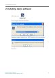
2 Installing demo software 2 Installing demo software Click’setup.exe’ Choose English and click OK button. Installation window will pop up if .NET Framework 2.0 is not installed. Click ‘Yes’. Software User’s Manual 800 & 500 Series Reader Demo (.
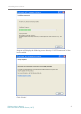
2 Installing demo software Click ‘Next’. Please refer to the following picture: Accept and click ‘Install’ to continue setup. Software User’s Manual 800 & 500 Series Reader Demo (.
2 Installing demo software Program will display the following screen directly if .NET Framework 2.0 has been installed. Click ‘Finish’. Software User’s Manual 800 & 500 Series Reader Demo (.
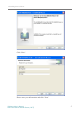
2 Installing demo software Click ‘Next’. Please enter your information and click ‘Next’. Software User’s Manual 800 & 500 Series Reader Demo (.
2 Installing demo software Select installation directory, click ‘Next’ Click ‘Install’ Software User’s Manual 800 & 500 Series Reader Demo (.
2 Installing demo software Click ‘Finish’ to close installation. After successful installation, the desktop shortcut " Software User’s Manual 800 & 500 Series Reader Demo (.
3 XCRF-800 Series Reader Demo User Manual The appropriate Start menu shortcuts will appear, as shown: Software User’s Manual 800 & 500 Series Reader Demo (.
3 XCRF-800 Series Reader Demo User Manual 3 XCRF-800 Series Reader Demo User Manual 3.1 Running the read demo Click [Start]—[Programs], select Invengo Demo v1.7 program group, and click ‘XCRF-800(500) Demo v1.7’ to run the XCRF-800(500) Series reader Demo. Or double click ‘XCRF-800(500) Demo v1.7’ on the desktop run the XCRF800(500) Series reader Demo. Click ‘Start 800 Series Reader Demo’: The screen appears: Software User’s Manual 800 & 500 Series Reader Demo (.
3 XCRF-800 Series Reader Demo User Manual 3.2 Connecting/disconnecting XCRF-800 Series reader 1. Selecting communication mode Three communication modes, including TCP/IP, COM (RS232) and USB, are available. Click ‘Comm. Port’ to select the desired communication mode. Notice: USB option will be available when USB device and the driver are installed: Install the USB driver as follows: Connect the reader with a USB cable, and apply power to the reader, the screen of ‘new hardware found’ appears.
3 XCRF-800 Series Reader Demo User Manual Click ‘Next’ Click ‘Next’ Software User’s Manual 800 & 500 Series Reader Demo (.
3 XCRF-800 Series Reader Demo User Manual Click ‘Finish’. The message of ‘New hardware is installed and ready for use’ displays. When the installation of driver is completed, the computer can communicate with the XCRF-800(500) Series reader via USB port. 2. Click ‘Connect’ button after the desired communication mode is selected. 3. Configuring COM port parameters The communication mode COM should be selected.
3 XCRF-800 Series Reader Demo User Manual the IP addresses of the PC and the reader are not in different segment, enter mapped IP address and port number or the reader and click “OK Connect” button to connect. 5. Successful connection After the successful connection, the Conn icon on the following screen turns green, and the software status bar indicates that ‘successful connection’. The screen appears. 6. Connection failed ‘Connect failed’ message will appear on the software status bar. 7.
3 XCRF-800 Series Reader Demo User Manual 3.3 Read and write operation 1. Configuration before read and write operation The screen appears: Figure: for XCRF-807 Reader Figure: for other readers Read mode: ‘Loop read’ and ‘Single read’ a) “single” mode: read only once, acquired tags will appear in the tag list. b) “loop” mode to read: continuously read tag operation will be performed until the stop read button is pressed. The acquired tags will show in the tag list.
3 XCRF-800 Series Reader Demo User Manual Set the power antenna/s, and click “OK”. RSSI: the antenna signal strength will display when selected. (Readers of specific models support this function.) UTC: UTC time will display when selected. (Readers of specific models support this function.) ASCII: ASCII format will be used to write tag data when selected; TID which is of 16 hex will be unaltered. 16 hex format will be used to write tag data when de-selected. 2. Read TID Click’ ‘to read TID number 3.
3 XCRF-800 Series Reader Demo User Manual 4.General read Click“ ”button to config reading parameters. TID len: specifies the length of the TID to read, usually set to 4 words (8 byte). Userdata ptr: specifies the offset of the user data to read. Userdata ptr must be within the memory bank. Userdata len: specifies the length of the user data to read. The sum of the offset and data length must be within the size of the memory bank. Click “OK” to set. 5.
3 XCRF-800 Series Reader Demo User Manual 7. Write EPC data Select a data in the data list. Click ‘ ’ button and the screen appears: Select tag (TID): click a data in the data list, and the TID number will be automatically added into the text box. (EPC number will be displayed in event of read EPC number.) Write data byte: The length of data byte to write which is even number will be automatically calculated according the input characters.
3 XCRF-800 Series Reader Demo User Manual Start address: in byte, start address is the start location for reading user data. (even number). Data length: the data length is calculated from the start address, the byte number of the data to read (even number) Tag user area data: read data results. OK: confirm to read user area data. Close: close the read user data area screen. Tip: EPC code defaults to 12 bytes.
3 XCRF-800 Series Reader Demo User Manual Tip: “Start address” + “data length” should not exceed the maximum size of bytes of user data. 10. General writes tag Select the data is the list, click ’ ’ button, and the screen appears: Select tag: Select the data is the list, and the TID number will automatically be added to the text box. (If the operation is to read EPC, it will be the EPC number.) Bank: select the operation bank. PWD: access password.
3 XCRF-800 Series Reader Demo User Manual 11. Exporting data Click’ ’ button, and the screen appears: Export Path: the directory to save the imported file. Click the ‘...’ button to explore the folders. File Group: input the file names, and the files exported will be automatically named by adding a sequent number. Export Solution: ‘Common’ enables the export of data listed in the box, and ‘sn + Tag NO.’ enables the export of sequence number + tag number. Export: exporting data.
3 XCRF-800 Series Reader Demo User Manual 3.4 Configuration menu 1. Frequency hopping management a) Frequency range: select ‘CN’, ‘US’ or ‘EU’ to switch the frequency range. If the frequency range is selected, the frequency of the reader will switch to the standard frequency of the selected region.
3 XCRF-800 Series Reader Demo User Manual Default option B: showing the frequency point of default option B listed in the frequency point list. Frequency point number: listing the frequency point number in the frequency point list. Import option: import the external frequency point options saved by demo software. Storing option: store the frequency point of the frequency point list in the external option file.
3 XCRF-800 Series Reader Demo User Manual by failed query, possibly indicating the feature to operate is not supported. Close screen is recommended. Configuring IP: modify the IP if needed Adjusting antenna power: adjust if needed. Or select the desired value (20-30). I/O control: configuring the ports. Session config: configuring the session. Q value: the XCRF-800 Series reader’s default Q value.
3 XCRF-800 Series Reader Demo User Manual 3. Configuring tag parameters Select a data is the data list. And the TID will automatically be added to the ‘select tag (TID)’ text box. Select TID: The system will automatically add the number of selected tags to the “Select Tag (TID)” text box. Input the desired number of tags to operate. Tag access password: input tag access password, the default is: ‘00000000’. Configuring access password: select and input new password.
3 XCRF-800 Series Reader Demo User Manual 4. Setting Read tag by I/O input trigger (applies to XCRF-807 reader) TID LG (doule bytes): Enter TID length of the tag to operate. User data Addr (double bytes): in byte, starting address for the user data area to read (even number). UD LG (double bytes): enter the length of user memory (even number). Trigger port: select the trigger port. Trigger type: Never, falling edge, rising edge. Antenna: select the number of antenna to operate.
3 XCRF-800 Series Reader Demo User Manual 5. EPC matching configuration Binary Code and hexadecimal digit are supported. EPC: EPC number data. Mask code: data to match, 0 indicates un-matched masked code. Configuring EPC matching: select the text box and edit. Canceling EPC matching: select and cancel the matching. OK: confirm or cancel the configuration according to the text box. Close: closing the screen. Software User’s Manual 800 & 500 Series Reader Demo (.
3 XCRF-800 Series Reader Demo User Manual 6. Filtering repeatedly acquired tag configuration. Repeatedly acquired tags filtering by time interval can be configured or canceled. Configuring repeated tag filtering: select and configure. Cancel repeated tag filtering: select and configure. Interval time: input or select the desired interval time. OK: Configure or cancel configuration. Close: closing the screen. 7. Setting reader clock Reader clock can be set in the above screen.
3 XCRF-800 Series Reader Demo User Manual 8. VSWR protection (only applies to XCRF-807 reader) Query (VSWR warning threshold): Query the current standing wave ratio warning threshold Set: Setting SWR warning threshold Query (standing wave ratio): forward volatage, backward voltage, and standing wave ratio. Software User’s Manual 800 & 500 Series Reader Demo (.
3 XCRF-800 Series Reader Demo User Manual 9. Over-temperature protection (only applies to XCRF-807 reader) Set: The over-temperature warning threshold saved to the reader. Query (over-temperature warning threshold): Query over-temperature warning threshold. Query (Motherboard temperature): The current board temperature. 10. Close Close the screen. Software User’s Manual 800 & 500 Series Reader Demo (.
4 XCRF-500 Series Reader Demo User Manual 3.5 Function Menu 1. Select and read tags Memory Section: select ‘TID Memory’, ‘EPC Memory’ and ‘user Memory’ Start Bit: the start position of the memory, in byte. Match Length: matching per bit. Memory Section: the section to match. OK: confirm the configuration. Close: close the screen. 2. Lock tag data area Select the data is the list. The TID will automatically be added to the ‘select tag Software User’s Manual 800 & 500 Series Reader Demo (.
4 XCRF-500 Series Reader Demo User Manual (TID)’ text box. TIDs can be set by user. Select tag (TID): input the tag TID. Data Section: select ‘All Memory’ , ‘TID", ‘EPC’ , ‘user’ , ‘access password , or ‘kill password’ . Lock Flag: select ‘lock’ or ‘unlock’. Access FWD: input tag access password. The default is: ‘00000000’. OK: confirm configuration. Close: close the screen. 3. Block Permanent Lock Lock Area: select the block to lock. Address of start block (BlockPtr) : 16 blocks comprise of a unit.
4 XCRF-500 Series Reader Demo User Manual Lock: to complete lock operation. Close: close the screen. 4. Activate EAS Alarm EAS alarm will be activated when specific tags in preset location are identified. EAS enabled: Configuring EAS: See Section 3.4 Alarm setting: 1. Visual alarm; 2. Audio alarm. Disabling EAS: click“ ”. 5. Kill tag Select the data in the list. The EPC will automatically be added to the ‘EPC number ‘text box. EPC Code: input the tag EPC. Tag Kill PWD: input the tag access password.
4 XCRF-500 Series Reader Demo User Manual 6. Querying the XCRF-800 Series reader parameters. Save: save the information in the external file. OK: Close the screen Software User’s Manual 800 & 500 Series Reader Demo (.
4 XCRF-500 Series Reader Demo User Manual 7. IO control (GPI signal monitoring applies to XCRF-807 reader) Query: query info of I/O port. Set: set the level of output port: high level or low level. Set (GPI signal change monitoring): Monitoring GPI signal changes.
4 XCRF-500 Series Reader Demo User Manual 8. Beep A warning tone gives off during operation when it is enabled. For example: a beep tone gives off when read tag is performed. Software User’s Manual 800 & 500 Series Reader Demo (.
Appendix 4 Troubleshooting 1 Serial Port Connection Failure Check whether the COM port of the reader is connected with the corresponding port. The serial link baud rate of computer and reader must be identical with that of reader. Whether the serial port cable is correctly connected. Disconnection or loose connection may disable the instructions from the computer to the Reader; 2 Network Port Connection Failure The default IP address is 192.168.0.210.
Appendix 5 How to operate readers remotely? Reader is equivalent to a network terminal. Demo software can be connected with IP address port (For connecting XCRF-800 Series reader see IP connection of 3.2; for IP address settings, see 3.4 in reader parameter settings; for connecting XCRF-500 Series reader, see IP Settings of 4.2; IP address settings, see 4.4 IP settings; reader port number is fixed at 7086); the reader can be operated when connection is established .
Appendix Appendix The CD-ROM contains setup installer, USB driver, API (including Invengo. ConfigFileClass.dll, Invengo.Order.dll, Invengo.XCRFAPI.dll, Invengo. XCRFReader.dll, log4net.dll, FreqType.xml, language folder) and so on. API interface function is the interface platform for the reader and background software which provides help for system integrators and end users. For addtional information on API interface function, please refer to .NET API Technical Reference Manual.
Warning This device complies with Part 15 of the FCC Rules. Operation is subject to the following two conditions: (1) this device may not cause harmful interference, and (2) this device must accept any interference received, including interference that may cause undesired operation. changes or modifications not expressly approved by the party responsible for compliance could void the user's authority to operate the equipment.
Corporate Headquarters Invengo Information Technology Co., Ltd. US Subsidiary Invengo Technology Corp. 3/F, No.T2-B, High-tech Industrial Park South, Shenzhen 518057, China 12801 Worldgate Drive, Suite 500 Herndon, VA 20170 U.S.A www.invengo.cn www.invengo.com Tel: (86) 755 26525585 Fax: (86) 755 26525277 Tel: 1 703 793 0085 Fax: 1 703 871 3901 intl@invengo.cn sales@invengo.