
User's Manual

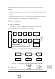

circuit. Then the signals was send to baseband unit. The baseband will decode the
received signal and then sends to PC via the communication interface of the
baseband unit.
The transmitting part of the RF unit will take the function of carrier generation,
carrier modulation, amplification and emission. The receiving part of the RF unit
will take the function of demodulation, amplify , compare etc.
The FPGA part of baseband will take the code/decode function to tag data.
MCU will take the function of communication with PC.
4 Usage and operation
4.1 Interrogator connection
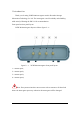
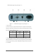
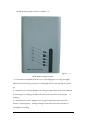
There are 4 antenna port on the XCRF-804 interrorgator .The output port of
antenna interface is SMA plug.
You can find antenna Cable with reversed SMA-Plug to N-Plug Connector in
the product accessories. Joint the antenna SMA plug to the SMA interface of
interrorgator and tight the bolt. The fit another port of the antenna cable with proper
antenna.
4.2 Interrogator usage and operation
Connect the device as stated above, and the interrorgator will work under the
control of PC command. Our company provide API function and interrogator
demo software .User can use the software to test the interrogator. Please read user
manual of the interrogator demo software to get the information about test procedure
and test method.
5 Usual failure analysis and exclusion
·When the interrorgator is power on the signal lamp is not lighted:
→power fault: check if the input alternating current power is normal. The
alternating current voltage should between 85V~265V;
→If the other signal lamp is light, there is MCU or FPGA fault in the device. Once
you meet this problem, you can only contact with Invengon company to repair the