
User's Manual

GENERAL INSTRUCTIONS LOCATION
8/5/02 PRELIMINARY DOCUMENT 3
Connections
The following section provides instructions for connecting to the Internet and
the procedural steps for applying power to the gateway.
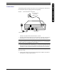
FIGURE 3. Invensys RF Gateway connections
1. Refer to FIGURE 3. Invensys RF Gateway connections, and connect your Invensys RF
Gateway to the Direct Cable Outlet Connection, as shown.
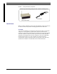
2. Plug the supplied power adaptor into the DC connector on the back of the Invensys
RF Gateway and insert the power plug into a wall socket with surge protection.
Note: There is NO power switch located on the Invensys RF Gateway unit. The unit is
“on” when you plug it in to a power outlet. Turning the gateway “off” is controlled via the
gateway software or by unplugging the power adapter.
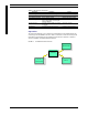
3. The Invensys RF Gateway will automatically run a 2-3 minute sequential self-test. The
LED light located on the front of the gateway will indicate the status of the process,
starting from a green blinking light through a solid green light if every test passes.
Note: You may see a very subtle orange blinking over the Solid Green light when the
data is processing
4. Follow the LED readouts and proceed accordingly. Refer to TABLE 1. LED indicator
descriptions for a listing of light indications.
Direct Cable Outlet
Connection
(EMSG-100-CR)
Power Adapter
DATA P O RT
INVENSYS QUALIFIED
TECHNICIAN