
User's Manual


INVENSYS RF LOAD CONTROL METER
4 PRELIMINARY DOCUMENT TD2001
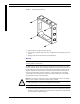
FIGURE 3. Mounting screw location
5. Refer to Wiring, on page 4 and wire the LCM.
6. After wiring is complete, replace the cover and tighten it securely with the four cover
screws.
7. Reapply power to the LCM and the electrical appliance.
Wiring
Caution: It is important to select cable that complies with the NEC code for the
electrical appliance being wired.
The EMSL-100 can control 120 VAC single-phase loads with current ratings up to 30A
resistive. The EMSL-200 can control 240 VAC single-phase loads with current ratings up
to 30A resistive. The LCM is connected in-line with the existing electrical wiring to the
appliance. Multiple-size knockouts are provided around the exterior perimeter of the
housing to accommodate a conduit connector or a cable clamp. Refer to the wiring
chart in Table 3 for terminal listings for both LCM models. Refer also to the example
wiring diagrams in Figure 5 through Figure 8.
Warning: You must turn off AC power to the electrical appliance that you are wiring.
Failure to turn off power could result in physical injury or death.
1. Shut off AC power to the electrical appliance being wired.
Caution: Use only NEMA 4x rated fittings in order to maintain the NEMA 4x rating.
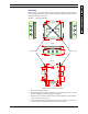
2. Connect the wires for the input (from the AC source) and output (to the electrical
appliance) as shown in Table 3 and in Figure 4. Refer to Figure 4 to see typical wiring
for a 120 VAC and a 240 VAC system.