ISM4343 Specification INVENTEK SYSTEMS ISM4343-WBM-L151 SiP and ISM4343-WBM-L54 Module eS-WiFi™ (embedded Serial-to-WiFi) Wi-Fi, BT & Arm Cortex M4 Combo SiP and Module Options 2.4 GHz 802.11 b/g/n + 5.1 BT/BLE + Cortex M4 Data Sheet DOC-DS-20074-5.
ISM4343 Specification Table of Contents 1 DETAIL DESCRIPTION ....................................................................................................... 4 1.1 Ordering Information for Inventek IWIN Firmware ...................................................... 4 2 OVERVIEW ........................................................................................................................... 5 3 FEATURES .......................................................................................
ISM4343 Specification 11.1 Application Circuit – Single Antenna ........................................................................... 41 11.2 ISM4343-WBM-L151 Application Circuit –Power Supply ......................................... 42 12 ISM4343-WBM-L151 DC POWER CONDITIONING AND DISTRIBUTION ................ 42 12.1 Power Conditioning ...................................................................................................... 42 13 ISM4343-WBM-L151 PCB LAYOUT GUIDELINES.................
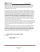
ISM4343 Specification 1 DETAIL DESCRIPTION Device Description Ordering Number ISM4343-WBM-L151 Wi-Fi + BT/BLE + Cortex M4 10 x 10 mm 151 Pad SIP ISM4343-WBM-L151 ISM4343-WBM-L54-C Wi-Fi + BT/BLE + Cortex M4 14.5 x 34mm 54 Pad LGA Module with Onboard Antenna Wi-Fi + BT/BLE + Cortex M4 Module 14.5 x 34mm 54 Pad LGA Module with Connector for External Antenna 2.4 Wi-Fi + BT/BLE SIP EVB (Evaluation Board) See 1.1 Below 2.
ISM4343 Specification 2 OVERVIEW The Inventek ISM4343-WBM-L151 SiP (10x10mm) and ISM4343-WBM-L54 module (15x34mm) offer a single-band IEEE 802.11 b,g,n-compliant MAC/PHY, and BT/BLE 5.1 radio. Channel bandwidth of 20MHz is supported for IEEE 802.11 b,g,n traffic with integrated ST Micro STM32F412 Cortex M4 MCU that runs the TCP/IP stack. This data sheet contains pinout information for both the ISM4343-WBM-L151 SiP and ISM4343-WBM-L54 module. The module includes either a chip antenna or U.
ISM4343 Specification and LTE, GPS, and Ultra-Wideband. An independent, high-speed UART is provided for the BT host interface. 3 FEATURES The ISM4343 SiP and module support the following WLAN, BT & MCU functions: • • • • • • • • • • • • • • • • • • • • STM32 ARM 32-bit CortexTM-M4 with a frequency up to 100 MHz o 1 Mbyte of MCU internal Flash o 256KByte of SRAM o ADC, I2C, I2S, GPIO, Timers Single-band 2.4 GHz b/g/n, 802.11b, 802.11g, 802.11n (single stream) o IEEE 802.11b 1 – 11 Mbps o IEEE 802.
ISM4343 Specification • • • • BT Low Energy (BLE) support BT Packet Loss Concealment (PLC) BT Wide Band Speech (WBS) Operating Temperature: -40℃ to 85℃ The BBC supports all BT 4.0 features, with the following benefits: • Dual-mode classic BT and classic Low Energy (BT and BLE) operation. • Low Energy Physical Layer • Low Energy Link Layer • Enhancements to HCI for Low Energy • Low Energy Direct Test mode • AES encryption 3.
ISM4343 Specification Separate approval is required for all other operating configurations, including portable configurations with respect to FCC CFR 47 Part 2.1093, and different antenna configurations. The antennas used with this module must be installed to provide a separation distance of at least 20cm from all persons, and must not be co-located or transmit simultaneously with any other antenna or transmitter, except in accordance with FCC multi transmitter product procedures.
ISM4343 Specification can be determined by turning the equipment off and on, the user is encouraged to try to correct the interference by one or more of the following measures: -Reorient or relocate the receiving antenna. -Increase the separation between the equipment and receiver. -Connect the equipment into an outlet on a circuit different from that to which the receiver is connected. -Consult the dealer or an experienced radio/TV technician for help.
ISM4343 Specification The radio transmitter has been approved by Industry Canada to operate with the antenna types listed above with the maximum permissible gain and required antenna impedance for each antenna type indicated. Antenna types not included in this list having a gain greater than the maximum gain indicated for that type, are strictly prohibited for use with this device.
ISM4343 Specification 5 BLOCK DIAGRAM Figure 1 : ISM4343-WBM-L151 has no antenna ISM4343-WBM-L54 has Onboard Antenna or U.FL for an External Antenna.
ISM4343 Specification 6.1 UART Interface The ISM4343-WBM-L151 shares a single UART for BT. The UART is a standard 4-wire interface (RX, TX, RTS and CTS) with adjustable baud rates from 9600 baud to 4.0 Megabaud. The interface features an automatic baud rate detection capability that returns a baud rate selection. Alternatively, the baud rate may be selected through a vendor-specific UART HCI command. The UART has a 1040-byte receive FIFO and a 1040-byte transmit FIFO to support EDR.
ISM4343 Specification UART Pins to connect when Using the ISM4343-WBM-L54 Module: Pin 21 22 Description USART1_RX USART1_TX STM32F412 PA10 PA9 6.2.1 Data Mode When the eS-WiFi module is interfaced serially, the serial interface needs to be configured for 8-bit data, no parity, and one stop bit - (8-n-1) using the IWIN AT Command firmware. 6.2.2 Flow Control The eS-WiFi module and WICED do not require or support Flow Control, so Flow Control should not be implemented. 6.2.
ISM4343 Specification 6.3 SPI (Serial Peripheral Interface Bus) – USES STM32F412 SPI4 The eS-WiFi module supports a custom SPI host interface with the IWIN SPI Firmware. The IWIN AT Command firmware for a SPI host interface is connected to SPI 4 bus on the module and is designed to utilize a command / data ready signal to help maximize Wi-Fi data throughput. The IWIN firmware uses SPI 4 for the interface and requires use of this Data Ready pin.
ISM4343 Specification SPI Slave Interface: Clock rate: 20MHz max. Width: 16-bit Mode: 0 Endian: Little Note: All commands to the eS-WiFi module must be post-padded with 0x0A (Line Feed) to an even number of bytes. All data from eS-WiFi module will be post-padded with 0x15(NAK) to an even number of bytes. 6.3.1 SPI Communication Overview: With the exception of initial cursor, all communication with the module happens synchronously.
ISM4343 Specification 6.3.2 SPI Command Phase: The Command Phase indicates the eS-WiFi module is ready to accept an IWIN AT Command. The command must include all delimiters and data for the command. Ex. S3=0010\r0123456789 The command must also be sent as one continuous SPI cycle, that is SSN must stay low for the complete command, delimiters, and data.
ISM4343 Specification 6.3.4 SPI Data Phase: The Data Phase indicates the eS-WiFi module has data ready for the Host to read. The eS-WiFi module will raise CMD/DATA READY and the Host will initiate a SPI cycle (lower SSN) and clock out 0x0A (Line Feed) until the CMD/DATA READY pin lowers signaling the end of the Data Phase. 6.3.
ISM4343 Specification 6.3.6 SPI AC Characteristics: Symbol Tf(sck) Tc(sck) Tsu(sck) Tc(byte) Tsu(ssn) Th(ssn) Min. Typ. 50 ns 15 us 8 * Tc(sck) 4 us 3 us DOC-DS-20074-5.3 Inventek Systems Page 18 Max.
ISM4343 Specification 6.3.7 I2S Timer Interface Characteristics 1. Guaranteed by characterization, not tested in production. 2. The maximum value of 256 x Fs is 50 MHz (APB1 maximum frequency). Note: Refer to the I2S section of RM0383 reference manual for more details on the sampling frequency (Fs). fMCK, fCK, and DCK values reflect only the digital peripheral behavior. The value of these parameters might be slightly impacted by the source clock accuracy. D CK depends mainly on the value of ODD bit.
ISM4343 Specification 6.4 ISM4343-WBM-L54-U External Antenna Connections ISM4343-WBM-L54-U module is designed for use with an external antenna via a connection using the U.FL connector. Item Connector Manufacturer Part No. Height Width DC Description U.FL series I-PEX Co., Ltd. 20279-001E-01 1.25 mm 2 mm 3.0 – 5.0 V On-Board Antenna Connector 6.
ISM4343 Specification 6.7 ISM4343-WBM-L54-U/C Pinout Description Pin No. Type 1 2 3 4 5 6 7 8 9 10 11 12 13 14 15 16 17 18 19 20 21 22 23 24 25 26 27 28 29 30 31 G I G I/O I/O I/O I/O I/O I/O I/O I/O I/O I/O I I I G I I/O G I/O I/O I/O I/O I/O I/O I/O I I I/O I/O Pin Definition Descriptions GND Ground VDD 3.3V GND Ground TMS JTAG TCK JTAG TDI JTAG TD0 JTAG TDRSTN JTAG ADC 4 / SPI_MOSI ADC Input Pins or SPI Interface. These SPI pins are also connected internally to ADC 3 / SPI_MISO the 2MB SPI Flash.
ISM4343 Specification Pin No. Type Pin Definition 32 I/O RES 33 I BOOT 0 Descriptions GPIO, see section Enable On-Board Microcontroller Boot Loader (See STM32F412 BOOT0 specification) Reset (See STM32F412 NRST specification) Ground Ground Ground Ground Ground Ground Ground Ground Ground Ground 34 35 36 37 38 39 40 41 42 43 44 I RSTN G GND G GND G GND G GND G GND G GND G GND G GND G GND G GND o Reserved Pins Pins currently available for designs using the WICED-SDK only. Pin No.
ISM4343 Specification 7 ISM4343-WBM-L151 Pinout Description 7.
ISM4343 Specification 18 19 GND NC - Ground Floating 20 BT_GPIO_3 I/O 21 MICRO_SPI2_MISO 22 MICRO_SPI2_MOSI 23 GND - Ground 24 VDD_3V3_3 PI DC supply for MCU and I/O 25 GND - Ground 26 NC - Floating 27 GND - Ground 28 VDD3V3_WiFi_IO PI DC supply for WIFI and I/O 29 GND - Ground 30 31 32 33 34 35 36 37 38 39 40 41 42 43 44 45 46 47 48 49 50 51 52 53 54 55 56 MICRO_USART1_TX MICRO_USART1_RX MICRO_USART1_CTS MICRO_USART1_RTS GND MICRO_JTAG_TMS GND MICRO_JTAG_TCK MICRO_J
ISM4343 Specification 57 58 BT_HOST_WAKE GND O - 59 VBAT PI 60 61 62 63 64 65 66 67 68 69 70 71 72 73 74 75 76 77 78 79 80 81 82 83 84 85 86 87 88 89 90 91 GND GND NC NC GND VDD_3V3 GND QUADSPI_BK1_IO1 QUADSPI_BK1_IO2 MICRO_I2S2_SD GND GND GND GND MICRO_SPI1_NSS MICRO_SPI1_SCK MICRO_SPI1_MISO GND QUADSPI_BK2_IO3 BOOT1/ QUADSPI_CLK QUADSPI_BK2_IO0 QUADSPI_BK2_IO1 MICRO_I2C2_SCL MICRO_I2C2_SDA MCIRO_SPI2_NSS MCIRO_SPI2_SCK MICRO_GPIO_27 MICRO_GPIO_25 NC NC VDD_USB GND MICRO_I2S2_MCK/ MICRO_USART6_TX M
ISM4343 Specification 96 97 98 99 100 101 102 103 NC NC NC GND NC GND MICRO_I2C1_SCL MICRO_I2C1_SDA I/O I/O 104 BOOT0 105 106 107 108 109 110 111 112 113 114 115 116 117 118 119 120 121 122 123 124 125 NC MICRO_GPIO_0 QUADSPI_BK2_NCS MICRO_GPIO_30 NC NC MICRO_I2S_DI GND GND GND GND GND MICRO_RST_N QUADSPI_BK1_IO0 MICRO_WKUP GND MICRO_ADC_IN2 SPI 4 data Ready GND QUADSPI_BK2_IO2 MICRO_GPIO_5 I/O I/O I/O I/O I/O I/O I/O I/O I/O I/O I/O 126 RF_SW_CTRL I/O 127 128 NC MICRO_GPIO_16 I/O 129 BT_GPI
ISM4343 Specification 136 137 138 139 140 141 142 143 NC MICRO_GPIO_26 NC NC NC NC MICRO_GPIO_28 MICRO_I2S2_WS I/O I/O I/O 144 BT_PCM_SYNC I/O 145 146 147 148 149 150 151 BT_PCM_OUT BT_PCM_IN PC13 GND GND MICRO_ADC_IN1 GND O I I/O I/O - Floating MCU_GPIO PD1 Floating Floating Floating Floating MCU_GPIO PB8 MICRO_I2S2_WS PB9 PCM Sync; can be master(output) or slave (input) PCM data output PCM data input sensing PC13 Ground Ground MCU_ADC_IN_1 PA1 Ground DOC-DS-20074-5.
ISM4343 Specification 8 ISM4343-WBM-L151 ELECTRICAL SPECIFICATIONS 8.1 Absolute Maximum Ratings Caution! The absolute maximum ratings indicate levels where permanent damage to the device can occur, even if these limits are exceeded for only a brief duration. Functional operation is not guaranteed under these conditions. Operation at absolute maximum conditions for extended periods can adversely affect long-term reliability of the device. Rating Power Supply Storage Temp Symbol MAX Celsius Value +4.
ISM4343 Specification 8.3 ISM4343 Operating Conditions and DC Characteristics Caution! Functional operation is not guaranteed outside of the limits shown in Table 5 and operation outside these limits for extended periods can adversely affect long-term reliability of this devices. ISM4343-WBM-L151 MCU VBAT Voltage Symbol VBAT Min 2.0 Typical 3.3 Max 3.6 Unit V GPIO I/O Supply VDD3V3_1 2.4 3.3 3.6 V GPIO I/O Supply VDD3V3_2 2.4 3.3 3.6 V GPIO I/O Supply VDD3V3_3 2.4 3.3 3.
ISM4343 Specification [2] Worst case power consumption represents active Wi-Fi 9 RF SPECIFICATIONS 9.1 BT RF Specifications Parameter Conditions Min Typical Max Unit Note: The specifications in this table are measured at the Chip port output unless otherwise specified: General Frequency Range GFSK, 0.1% BER, 1 Mbps π/4-DQPSK, 0.01% BER, 2 Mbps 8-DPSK, 0.01% BER, 3 Mbps - RX sensitivity Input IP3 Maximum input at antenna 2402 - 2480 MHz - -93.5 - dBm - -95.5 - dBm - -89.
ISM4343 Specification Parameter: BT Low Energy Condition Min Condition: 25 Deg. C, includes both Wi-Fi and BT Transmitter and baseband are Tx Mode both operating, 100% Receiver and baseband are Rx Mode both operating, 100% Typical Max Unit 35 mA 16 mA Table 9: BLE Current Consumption (M4 MCU not calculated) 9.2 WLAN RF Specifications The ISM4343-WBM-L151 includes an integrated single-band direct conversion radio that supports the 2.4 GHz band. 2.
ISM4343 Specification Item Conditions Min Typical Max Unit Tx/Rx switch time Rx/Tx switch time Power-up and powerdown ramp time Including TX ramp down Including TX ramp up - - 5 2 μs μs DSSS/CCK Modulations - - <2 μs Table 10: 2.4 GHz Band General RF Specifications (default voltage is 3.3V) WLAN 2.4 GHz Receiver Performance Specification Parameter Condition/Notes Max Unit Frequency Range 2400 2500 1 Mbps DSSS -97.9 2 Mbps DSSS -96.9 5.5 Mbps DSSS -92.5 11 Mbps DSSS -90.
ISM4343 Specification RX sensitivity (10% PER for 4096 octet PSDU)ª,ᶜ Defined for default parameters: Mixed mode- 800n ns GI, and non-STBC. RX sensitivity (10% PER for 4096 octet PSDU)ª,ᵇ Defined for default parameters: GF, 800 ns GI, and non-STBC. MCS 7 -72 dBm 20 MHz channel spacing for all MCS rates (Mixed mode) MCS0 -91 dBm MCS 1 -87.9 dBm MCS 2 -85.5 dBm MCS 3 -82.8 dBm MCS 4 -79.9 dBm MCS 5 -76.2 dBm MCS 6 -74.6 dBm MCS 7 -72.6 dBm 40 MHz channel spacing for all MCS rates (Mixed mode) MCS0 -89.
ISM4343 Specification 802.11g Receiver Item Receiver minimum input level sensitivity (PER<10 %) Receiver maximum input level (PER<10%) Condition 6Mbps Min. -82* Typ. -88 Max. Unit 9Mbps -81* -87 dBm dBm 12Mbps -79* -85 dBm 18Mbps -77* -83 dBm 24Mbps -74* -80.5 dBm 36Mbps -70* -78.5 dBm 48Mbps -66* -74 dBm 54Mbps -65* -72 dBm 6/9/12/18/24/36/48/54 -20* dBm Table 13: WLAN 2.4 GHz 802.11g Receiver Performance Specifications 802.
ISM4343 Specification 802.11b Transmit Item Transmit output power level Transmit center frequency tolerance Transmit spectrum mask Condition Min. 1M/2M/5.5M/11M Typ. Max. 17 -20 dBm 20 ppm Fc-22MHzFc+22MHz(1/2/5.5/11Mbps; channel 1~13) -50* dBr Transmit power -on Transmit power down Transmit modulation accuracy 0 Unit 10% ~ 90 % 0.3 2* us 90% ~ 10 % 1.5 2* us 1/2/5.
ISM4343 Specification Transmit spectrum mask @ 20MHz -28* dBr @ 30MHz -40* dBr Max. Unit Table 16: WLAN 2.4 GHz 802.11g Transmit Performance Specifications 802.11n Transmit Condition Item Typ. HT20 MCS 0~7 12 dBm HT20 MCS 7 (Turboqam) 10 dBm Transmit output power level Transmit center frequency tolerance Transmit modulation accuracy Min.
ISM4343 Specification DH5 packet Drift rate ±8 ± 40 kHz 5 20 kHz/50μs 175 kHz Frequency Deviation 00001111 sequence in payloada 140 155 10101010 sequence in payloadb 115 140 kHz 1 MHz Channel spacing • • This pattern represents an average deviation in payload. Pattern represents the maximum deviation in payload for 99.9% of all frequency deviations. Table 18: BT Transmit Performance Specifications Parameter Mode and Condition Min. Typ. Max.
ISM4343 Specification 9.3 ISM4343-WBM-L54-U External Antenna The Inventek U.FL PCB antenna is certified for FCC, IC and CE. The part number is W24P-U. It is a single band 2.4 GHz PCB antenna with a U.FL connector. The Inventek W24P-U PCB antenna datasheet can be found on the Inventek Website. 9.4 Environmental Specifications Item Operating temperature range Storage temperature range Humidity (Non-Condensing, relative humidity) Description -40 deg. C to +85 deg. C -40 deg. C to +125 deg.
ISM4343 Specification 10 Additional Information 10.1 Communications Interfaces 10.1.1 I2C Interface Characteristics 1. Guaranteed by design, not tested in production. 2. fPCLK1 must be at least 2 MHz to achieve standard mode I2C frequencies. It must be at least 4MHz to achieve fast mode I2C frequencies, and a multiple of 10 MHz to reach the 400 kHz maximum I2C fast mode clock. 3.
ISM4343 Specification DOC-DS-20074-5.
ISM4343 Specification 11 ISM4343-WBM-L151 Hardware Design Recommendations 11.
ISM4343 Specification 11.2 ISM4343-WBM-L151 Application Circuit –Power Supply JP27 header3 2 FB4 1 2 C25 10uF MMZ1608B301C D2 EXT_5V WIFI_EXT_v oltage U6 1 R86 0R R87 680 2 3 VDD 5 Vout VBAT 2 C29 GND CE FB6 1 1 1 2.2uF GND1 1 10uF C24 33NF 2 C23 1 C22 1 5V 4 NC MMZ1608B301C 10uF C31 C32 C33 DNI DNI 4.7uF EXT_5V WIFI_EXT_v oltage XC6222B331MR-G FB7 1 LED/0603 VDD_3V3 2 MMZ1608B301C C34 C35 C36 DNI DNI 4.7uF C37 C38 C39 DNI DNI 4.
ISM4343 Specification Each regulator output must be connected directly to its recommended output capacitor per the Power source. All the power supply pins should be decoupled. Additional filtering and bypassing of the RF supply voltages 13 ISM4343-WBM-L151 PCB LAYOUT GUIDELINES 13.1 DC Power Use wide traces for power supply lines. Know the maximum currents being carried on each power supply trace, and make the trace widths proportionate to the current (especially for long trace lengths).
ISM4343 Specification • Clear internal layer (or layers) of metal. This improves micro-strip, CGW, and strip-line geometries, allowing wider traces. • Fill the areas along both sides of traces with ground to improve isolation, but provide adequate clearance to minimize co-planar capacitance and leakage. These ground-filled areas are integral to CGW designs. • Use several ground vias along both sides of the signal traces to connect RF ground-fill areas to the internal RF ground plane.
ISM4343 Specification 14.1 ISM4343-WBM-L151 Recommended PCB Footprint (Bottom View) Dimension Measurement Unit: mm Note: 1. 2. - Please use Un-Solder Mask to design the Module Footprint. There are three types pad size in the Module. Type A: Pad size: 0.424 x 0.424mm2 & Solder Mask size: 0.524 x 0.524 mm2 Type B: Pad size: 0.275 x 0.325mm2 & Solder Mask size: 0.35 x 0.4 mm2 Type C: Pad size: 2.7 x 2.7mm2 & Solder Mask size: 2.8 x 2.8 mm2 DOC-DS-20074-5.
ISM4343 Specification 14.2 ISM4343-WBM-L151 Recommended PCB Footprint (Top View) The X-Y Central Location Coordinates Unit: mm (Drawn dimensions with chip 0,0 at bottom right corner) Top View (0,0) PIN NUMBER 1 2 3 4 5 6 7 8 9 10 11 12 13 14 PAD Size (mm) 0.275 0.275 0.275 0.275 0.275 0.275 0.275 0.275 0.275 0.275 0.275 0.275 0.275 0.275 x x x x x x x x x x x x x x 0.325 0.325 0.325 0.325 0.325 0.325 0.325 0.325 0.325 0.325 0.325 0.325 0.325 0.325 Solder Mask Size (mm) 0.35 0.35 0.35 0.35 0.35 0.
ISM4343 Specification 15 16 17 0.275 x 0.325 0.275 x 0.325 0.275 x 0.325 0.35 x 0.4 0.35 x 0.4 0.35 x 0.4 -2 -1.5 -1 0.385 0.385 0.385 18 0.424 x 0.424 0.524 x 0.524 -0.35 0.35 19 20 21 22 23 24 25 26 27 28 29 30 31 32 33 34 35 36 37 38 39 40 41 42 43 44 45 46 47 48 49 0.325 0.325 0.325 0.325 0.325 0.325 0.325 0.325 0.325 0.325 0.325 0.325 0.325 0.325 0.325 0.325 0.325 0.424 0.275 0.275 0.275 0.275 0.275 0.275 0.275 0.275 0.275 0.275 0.275 0.275 0.275 0.4 x 0.35 0.4 x 0.35 0.4 x 0.35 0.4 x 0.
ISM4343 Specification 50 51 52 53 54 55 56 57 58 59 60 61 62 63 64 65 66 67 68 69 70 71 72 73 74 75 76 77 78 79 80 81 82 83 84 85 0.275 0.275 0.275 0.275 0.424 0.325 0.325 0.325 0.325 0.325 0.325 0.325 0.325 0.325 0.325 0.325 0.325 0.325 0.325 0.325 0.325 0.325 0.424 0.275 0.275 0.275 0.275 0.275 0.275 0.275 0.275 0.275 0.275 0.275 0.275 0.325 x x x x x x x x x x x x x x x x x x x x x x x x x x x x x x x x x x x x 0.325 0.325 0.325 0.325 0.424 0.275 0.275 0.275 0.275 0.275 0.275 0.275 0.275 0.275 0.
ISM4343 Specification 86 87 88 89 90 91 92 93 94 95 96 97 98 99 100 101 102 103 104 105 106 107 108 109 110 111 112 113 114 115 116 117 118 119 120 121 0.325 0.325 0.325 0.325 0.325 0.325 0.325 0.325 0.325 0.325 0.325 0.275 0.275 0.275 0.275 0.275 0.275 0.275 0.275 0.275 0.275 0.275 0.275 0.325 0.325 0.325 0.325 0.325 0.325 0.325 0.325 0.325 0.325 0.325 0.325 0.275 x x x x x x x x x x x x x x x x x x x x x x x x x x x x x x x x x x x x 0.275 0.275 0.275 0.275 0.275 0.275 0.275 0.275 0.275 0.275 0.275 0.
ISM4343 Specification 122 123 124 125 126 127 128 129 130 131 132 133 134 135 136 137 138 139 140 141 142 143 144 145 146 147 148 149 150 151 0.275 0.275 0.275 0.275 0.275 0.275 0.275 0.325 0.325 0.325 0.325 0.325 0.325 0.325 0.275 0.275 0.275 0.275 0.275 0.275 0.275 0.275 0.325 0.325 0.325 0.325 0.325 0.325 0.325 2.7 x x x x x x x x x x x x x x x x x x x x x x x x x x x x x x 0.325 0.325 0.325 0.325 0.325 0.325 0.325 0.275 0.275 0.275 0.275 0.275 0.275 0.275 0.325 0.325 0.325 0.325 0.325 0.325 0.325 0.
ISM4343 Specification 14.3 ISM4343-WBM-L151 Recommend Stencil: Unit: mm DOC-DS-20074-5.
ISM4343 Specification 15 ISM4343-WBM-L54 Mechanical Specifications 15.1 ISM4343-WBM-L54 Dimensions top view (mm) The ISM4343-WBM-L54 module is footprint compatible with Inventek’s standard 44 pin LGA footprint minus the extra 10 inside pads (Pins 45-54). 15.2 ISM4343-WBM-L54 Module’s Dimensions Top View (mm) Chip Antenna Keep out Area ” Keep out” area should ideally have the antenna hanging the side of the PCB for best performance.
ISM4343 Specification Figure 2 Module Dimensions - Top View 16 ISM4343-WBM-L54 Antenna Keep-Out Area There should be no copper (ground or traces) in the antenna keep-out area shown in Section 15.1. In all cases the keep-out area must be placed as close to the PCB board edge as possible. The keep out area should be extended to the edge of the PCB board. If the Module or SiP/Antenna cannot not be placed in a corner it can be moved along the edge of the PCB board toward the center line (but exceeding it).
ISM4343 Specification 17 Product Compliance Considerations RoHS: Restriction of Hazardous Substances (RoHS) directive has come into force since 1st July 2006 all electronic products sold in the EU must be free of hazardous materials, such as lead. Inventek is fully committed to being one of the first to introduce lead-free products while maintaining backwards compatibility and focusing on a continuously high level of product and manufacturing quality.
ISM4343 Specification 19 ISM4343-WBM-L54 Reflow Profile • • • Reference the IPC/JEDEC standard. Peak Temperature: <250°C Number of Times: ≤2 times DOC-DS-20074-5.
ISM4343 Specification 20 Packaging Information 20.1 MSL Level / Storage Condition 20.2 Device baking requirements prior to assembly Boards must be baked prior to rework or assembly to avoid damaging moisture sensitive components during localized reflow. The default bake cycles is 24 hours at 125C. Maintaining proper control of moisture uptake in components is critical.
ISM4343 Specification 21 Revision Control Document: ISM4343-WBM-L151 External Release Date Author 1/15/2015 AS 12/17/2015 AS 5/30/2017 AS 8/22/2017 KT 4/12/2018 AS 1/14/2019 MT Revision 1 1.1 1.2 2 2.1 3.0 9/8/2019 RB 3.1 4/1/2021 5/17/2021 8/20/2021 RB SP RB 3.2 3.3 3.4 3/30/2022 RB 3.5 4/13/2022 RB 3.6 Wi-Fi + BT/BLE + Cortex M4 Module DOC-DS-20074-3.
ISM4343 Specification Inventek reserves the right to make changes to the Software without notice. Inventek does not assume any liability arising out of the application or use of the Software or any product or circuit described in the Software. Inventek does not authorize its products for use in any products where a malfunction or failure of the Inventek product may reasonably be expected to result in significant property damage, injury, or death ("High Risk Product").