
Data Sheet


ISM4343 Specification
DOC-DS-20074-5.3
Inventek Systems
Page 15
SPI Slave Interface:
Clock rate: 20MHz max.
Width: 16-bit
Mode: 0
Endian: Little
Note: All commands to the eS-WiFi module must be post-padded with 0x0A (Line Feed) to an
even number of bytes.
All data from eS-WiFi module will be post-padded with 0x15(NAK) to an even number of bytes.
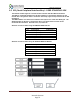
6.3.1 SPI Communication Overview:
With the exception of initial cursor, all communication with the module happens synchronously.
In other words, the SPI Master must always poll for every asynchronous event.
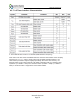
A typical command flow is provided flow. This is an example using the Direct Connect Soft AP
with a TCP communication server.
SPI Master
SPI Slave (eS-WiFi)
Description
“\r\n> “
Prompt
“AS=0,ABC\r\x0A”
"\r\n\r\nOK\r\n> "
Set Access Point SSID
“AD\r\ x0A”
"\r\n\r\nOK\r\n> "
Start AP - Direct Mode
"P1=0\r\ x0A”
"\r\n\r\nOK\r\n> "
Set TCP Protocol
"P4=2000\r"
"\r\n\r\nOK\r\n> "
Set TCP Port
"P5=1\r\ x0A”
"\r\n\r\nOK\r\n> "
Start TCP COMM Server
"MR\r\ x0A”
"\r\n[SOMA]...[EOMA]\r\nOK\r\n>
"
Read Messages
Note: [SOMA] - Start of Message Asynchronous, [EOMA] - End of Message Asynchronous
The SPI communication is always 16-bit and can be sustained up to 20MHz. The eS-WiFi
module after power up or reset will raise CMD/DATA READY pin to signal that the first Data
Phase has started. In this mode, the SPI Host must fetch the cursor. As provided by the example
above, this is the only time host needs fetch data from slave without issuing a command.
The Host will initiate a SPI cycle (lower SSN) and clock out 0x0A (Line Feed) until the
CMD/DATA READY pin lowers signaling the end of the Data Phase. The data received will be
0x0d (CR) 0x0A (LF) 0x3E (>) 0x20 (SP).
The next rising edge of the CMD/DATA READY pin signals the Command Phase.