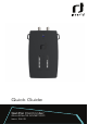
Quick Guide SatPal Controller IDLU-SPAL03-OOOBT-OPP Item: 5415
En Contents Languages English..............................................................................................................................................4 Deutsche .......................................................................................................................................45 English Notices ...........................................................................................................................................4 Quick User Guide.................
Notices Copyright No part of this manual may be copied, reproduced, used or translated in part or whole without FTA Communication Technologies S.à r.l. (hereinafter “FTA”) prior consent in writing. CE Declaration of Conformity Hereby, FTA Communication Technologies S.à r.l.
FTA warrants the product as being free from defects in material and workmanship for a period of 24 months starting from the date of production indicated on it (encoded into the serial number printed on the unit). This product is designed for the reception and measurement of satellite television and radio signals in satellite TV installations. The warranty does not apply for products used for other purposes than those specified herein.
Quick User Guide Install the SatPal™ application Download and install the application on your smartphone from the Apple iTunes store or Android Google Play Store by searching for “SatPal” from Inverto Digital Labs. Note: Layouts and usage of the SatPal™ application are slightly different between Apple iOS and Android OS, moreover appearance depend on your screen size. You may need to scroll with your finger to see items. This quick user guide is based on Apple iOS.
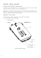
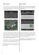
En 1. LNB/Switch (DC Out) – F-type Connect to the LNB/ Multiswitch to be setup/programmed. 2. Receiver (DC IN, RF Loop) – F-type Power supply (10 V ~ 20 V/13 W max.) from a receiver, a power inserter or a power supply. 3. Status LED ▪ Blinking white: communication with LNB/Multiswitch ▪ Steady read: configuration of connected dCSS device is not the same as configuration stored in the SatPal™ Controller (standalone mode) 4.
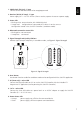
Connect the SatPal™ Controller Connect the SatPal™ Controller to power (e.g. to a power bank or an AC/DC adapter). The power bank can be fixed with a battery holder band on the back of the SatPal™ Controller, see, Figure 3: SatPal Controller with power bank. side of the power bank. For battery saving, it is recommended to power off the battery’s port or disconnect the battery whenever you are not using the SatPal™ Controller.
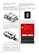
Tap on “Connect Now” to connect the application to the SatPal™ Controller; see Figure 6: SatPal™ Controller not connected. Attention! Connecting over Bluetooth is only possible via the application and not from the generic iOS/Android Bluetooth settings. Home screen After successful connection the Bluetooth LED at the SatPal™ Controller will stop flashing and the Bluetooth icon at the smartphone will show up. The home screen as per Figure 7: Home screen appears.
Sat finder Home » Sat meter The Sat finder function allows to align easily a satellite dish towards a desired satellite position with the aid of GPS and a map of current location, see Figure 10: Sat finder. The Sat meter function can measure satellite signals and helps the user to analyse and optimize the reception quality if needed. See Figure 11: Sat meter menu. Figure 10: Sat finder Figure 11: Sat meter menu Go with the smartphone to the position where the satellite dish should be installed.
Home » Sat meter Tap on “LNB Configuration” to select the right LNB type and to set the parameters of your connected LNB device. For dCSS dynamic you can change the parameters for the dish position (A, B, C, D), the frequency of the UB, the UB number, the protocol type (SatCR/ EN50494, dCSS/EN50607), low band LO- and high band LO-frequency, see Figure 13: LNB configuration, dCSS.
Custom satellite for Sat meter Home » Sat meter » Select satellite » choose “* Custom” Tap on the icon with the pencil to generate or edit a TP list for a satellite named “* Custom”, see Figure 15: Custom satellite, TP list. If the desired satellite is not available in the list of satellites, you can edit the “* Custom” satellite entry with the corresponding TPs. Select “* Custom” at the top of the satellite list, see Figure 14: Custom satellite.
TP list modification of existing satellite entries Home » Sat meter En Tap on a TP entry to edit the TP data for the TP frequency, polarization, symbol rate and DVB system, see Figure 16: Custom satellite, edit TP. Choose the desired satellite at “Select satellite” and tap on the icon with the pencil to edit the predefined TP list for this satellite, see Figure 17: TP list of existing satellite.
and to go one screen backwards. Custom TP lists Home » Sat meter » TP Lists Tap on the “+” sign to create a new TP list, a screen as depicted in Figure 19: New TP list will appear. To have a maximum flexibility for different measurement and report scenarios you can create, edit and store customized TP lists according to your needs and installation setups. TP lists can be designed and created offline to be more efficient for field installations and for fast changes between different measurement setups.
Tap on “Save” at the bottom to save the new created or modified TP list. If your SatPal™ Controller is connected to the antenna system aligned to the satellite for what the TP list has been created you will see immediately a signal level, see Figure 21: New created TP list. En A selected TP will be marked with a check and is listed at the bottom field, see Figure 20: Created TP list.
Sat meter measurements Sat meter options Tapping on the “signal bars” in Figure 11: Sat meter menu or in Figure 21: New created TP list, will display detailed signal meters as seen in Figure 22: Signal strength. Tap on “Options” as depicted in Figure 22 : Signal strength to change parameters for the Signal meters and buzzer. See Figure 23: Sat meter settings.
Satellite footprints Tap on “Spectrum” in screen Figure 22: Signal to see the spectrum of the selected transponder. If your SatPal™ Controller is connected to a universal LNB or multiswitch system or to a legacy configured dCSS multswitch you will get a list of best fit satellites to the measured signal pattern. See Figure 24: Spectrum. Note: The satellite footprint information will work for set spans between 200 MHz and 1200 MHz.
Signal constellation Install & Report This screen displays the constellation diagram of the chosen TP to allow you to analyze the signal quality and further optimize your installation. The Install & Report function allows you to record the signal quality of your installation and generate an installation report including name of installer, TP signal parameters, location data, inventory list and photo(s) of the installation.
En Swipe the entire screen to the left for the next step, which is “Installation location”. With the aid of GPS coordinates you will see the location. The user can change or add the information for “Location name”, “Street / House no.” and “City” to be shown in the site installation report, see Figure 27: Installation location. Figure 28: Equipment list Tap on “+” to add a new equipment item. Figure 29: New equipment will appear.
Type in your model code, your serial number and fill out the description field. If you have an Inverto LNB or Multiswitch device tap at model on “>”. Screen Figure 31: New equipment Item# appears. If the device has a barcode sticker you can tap on “scan” and use your smartphone camera towards the barcode to scan it. A successful scan will be noticed by a sound or vibration of the smartphone. Moreover, you can see then the serial number at the field “Serial”, see Figure 30: After device scan.
If you want to delete an item just slide the bar of the respective item to the right and tap on “Remove”. See Figure 33: Remove equipment item. Figure 32: Equipment list with items Figure 33: Remove equipment item En Then tap on “Save” to save the equipment information. Figure 32: Equipment list with items shows an example with two items. Follow the same procedures to add more devices for the installation documentation if required.
Swipe again the screen to the left for the “Photo documentation” and take one or more pictures by tapping on “Take Photo”, see Figure 34: Photo documentation. Swipe again the screen to the left, see Figure 35: Installation summary. Figure 35: Installation summary Figure 34: Photo documentation Pictures can be deleted or re-taken at this section if needed. 22 You can check again the “Signal Quality” of the chosen TPs and you will see the location data used for the report.
En Tap on “Send” to send the report. Screen as depicted in Figure 36: Send installation report will be shown. Figure 36: Send installation report The report will be sent to the email address as set at ‘target e-mail’ under the section Settings (“Home » Settings”, or as described on page 36: Settings).
The report will be attached in pdf, xml and csv format. It includes all prior inserted data. As example see an excerpt in Figure 37: Installation report of a generated installation report in pdf format.
Home » Report History Tapping on a record on the list will display the respective report. See Figure 39: Sent report as example. At this section you will find a list of sent reports stamped with date, time and location. See Figure 38: Report history. En Report History Figure 39: Sent report Figure 38: Report history By tapping on “Purge History” at the bottom you can purge all sent reports. A window to confirm will pop up prior deletion.
Unicable II™ toolbox Home » Unicable II™ toolbox Unicable II™ configuration with LNB For example, a screen as depicted in Figure 41: Unicable II™ Connected Device, LNB will be displayed. Home » Unicable II™ toolbox » upper rectangle At this section you can read and edit the configuration of connected Unicable II™ LNB or MSW devices. Scope and possible changes depend on connected device. Find also further information on page 33: Unicable II™ Configuration Editor.
Tap on “Mode” to change the operating mode of the LNB. For an Unicable II™ LNB either “Dynamic” or “Static” mode. See Figure 43: Mode LNB. En When the download of the configuration data is completed, a screen as depicted in Figure 42: Configuration, LNB will be displayed. Figure 42: Configuration, LNB You can see the operating mode of the device and further down a list of configured UB’s with assigned Unicable protocol type(s), UB frequency and bandwidth.
Tap on a particular UB row below the section “Output” to change the particular UB configuration. See Figure 44: Configuration User Band, LNB. To disable a UB swipe the row of the required UB to the right and tap on “Disable”, see Figure 45: Disable, Enable UB, LNB.
A screen as depicted in Figure 47: Unicable II™ Connected Device, MSW will be displayed. Home » Unicable II™ toolbox En Unicable II™ Configuration with Multiswitch When an Unicable II™ Multiswitch is connected to the SatPal™ Controller, the screen as in Figure 46: Unicable II™ Configuration, MSW will be displayed. Figure 47: Unicable II™ Connected Device, MSW Tap on “Configuration” in order to read the configuration from the connected Multiswitch device.
When the download of the configuration data is completed, a screen as depicted in Figure 48: Configuration, MSW will be displayed. Home » Unicable II™ toolbox » upper rectangle » configuration » Advanced options By tapping on “Advanced options”, you can set further parameters like LO-frequencies or the start-up mode, depend on connected device. By tapping on “Save Configuration” the changes will be saved. By tapping on “Commit changes” the configuration will be uploaded to the connected device.
Unicable II™ diagnostic Home » Unicable II™ toolbox » “upper rectangle” » Diagnostic En To disable a UB swipe the row of the required UB to the right and tap on “Disable”, see Figure 50: Disable, Enable UB, MSW. After tapping on “Unicable II™ toolbox” followed by tapping on the “upper rectangle” of connected device tap on “Diagnostic”.
Unicable II™ diagnostic, Spectrum Home » Unicable II™ toolbox » “upper rectangle” » Diagnostic » Spectrum” To change the capture parameters, tap on “Change” on the spectrum display. You will see changeable parameters as depicted in Figure 53: Spectrum Capture Parameter. Tap on “Spectrum” to display in real time the spectrum at the input of the connected LNB or Multiswitch Figure 52: Spectrum diagnoses. Figure 53: Spectrum Capture Parameter Tap on “Apply” to apply settings.
Unicable II™ Configuration Editor Home » Unicable II™ toolbox » “upper rectangle” » Diagnostic » Usage Information Home » Unicable II™ toolbox » “lower rectangle”» Configuration Editor Tap on “Usage information” to display information, depending on the connected model, about the device temperature, number of resets and activated UB’s over a time axis, see Figure 54: Usage information as example. At this section you can create your own Unicable II™ configuration files for Unicable II™ capable devices.
In case of no device is connected and you tap on “Home » Unicable II™ toolbox” a screen as depicted in Figure 55: Unicable II™ Configuration Editor will be displayed. Figure 55: Unicable II™ Configuration Editor 34 Tap on “Home » Unicable II™ toolbox » Configuration Editor ‘lower rectangle’’” to come to the section “Local File System” as depicted in Figure 56: Local File System. As example two configuration files are stored locally.
If you want to delete a configuration file swipe the “filename row” to the right and tap on “Delete”, see Figure 58: Delete configuration file. Figure 57: New Configuration Figure 58: Delete configuration file At this screen you can chose the Unicable II™ device for which a configuration should be generated and later maybe modified. Scroll the wheel under “Device:” until the desired 4-digit Inverto item number is displayed.
If you swipe a filename of the Dropbox account to the right, you can tap on “Delete” to delete the file in the Dropbox account or you can tap on “Copy to Local File System” to copy the file to the local file system. See Figure 59 With Dropbox account linked. Figure 60: Upload configuration To upload the configuration file to a connected device (ODU) tap on “Upload to ODU”.
Home » Settings Tap on “Settings” to enter the setting section. See Figure 62: Setting section. At this section you can see details of the connected SatPal™ Controller, enter personal details of the installer, set the e-mail address where to send the installation reports to and to link with a Dropbox account. En Settings Tap “Home” to see the “Settings” menu item. See Figure 61: Home menu items.
SatPal™ Controller settings Home » SatPal Controller At this section you can trigger for a connected SatPal™ Controller a firmware upgrade, set a TP Configuration for the standalone mode, to define the function of the “User button” and to trigger a reset to factory defaults, see Figure 63: SatPal™ Controller Menu. User Button Function for standalone mode Home » SatPal Controller » User Button Function The SatPal™ Controller has a small button, right beside the micro USB socket for “PC (Data Only)”.
Home » SatPal Controller » TP Configuration For instance, to setup a configuration for TP1, tap on the “row of TP1”. A screen as depicted in Figure 66: TP Configuration, TP1 will be displayed. En TP Configuration for standalone mode At this section you can configure four TP’s for the toggling mode while the SatPal™ Controller is used in standalone mode as described on page 40: User Button Function for standalone mode.
See Figure 67: TP Configuration, LNB Type as example for a dCSS LNB setup. Reset SatPal™ Controller to factory defaults Home » SatPal Controller » Reset to Factory Defaults In some cases, it might be required to reset the SatPal™ Controller to the factory default settings. Tap on “Reset to Factory Defaults” at “Home » SatPal Controller”. A window with a warning will pop up. To trigger the “Reset to factory defaults” tap on “Yes”. See Figure 68 Reset to Factory Defaults.
BER C/N dCSS DiSEqC IF LKM LNB LOF MER MSW ODU STB TP UB En Abbreviations Bit Error Rate Carrier to Noise ratio Digital Channel Stacking System Digital Satellite Equipment Control Intermediate Frequency Link margin Low Noise Block Converter Local oscillator frequency Modulation Error Ratio Multiswitch Outdoor Unit: e.g.
Specifications Frequency range Satellite (LNB/Multiswitch and Receiver ports) 950 MHz ~ 2150 MHz Bluetooth 2.4GHz Interfaces LNB/Multiswitch 1x Satellite IF + 13 V/18 V DC out + 0 kHz/22 kHz, F-type Receiver 1x Satellite IF loop-through-out + 13 V/18 V DC in, F-type PC (Data) 1x PC data communication, micro USB Bleutooth (Wireless data) 1x Bluetooth low energy (IEE 802.15.1 BT4.0) DC In 1x DC input, micro USB Loop-through loss (Satellite) 1dB max.
........................................................................................................................................................... En Notes ........................................................................................................................................................... ........................................................................................................................................................... .................................
Deutsch De En Inhalt Mitteilung.......................................................................................................................................46 Kurzanleitung.................................................................................................................................48 SatPal™ Controller anschließen......................................................................................................50 Starten der SatPal™ Applikation..............................
Mitteilung Copyright Kein Teil dieses Handbuchs darf ohne vorherige schriftliche Zustimmung von FTA Communication Technologies S.à r.l. (im Folgenden “FTA”) ganz oder teilweise kopiert, vervielfältigt, verwendet oder übersetzt werden. CE-Konformitätserklärung Hiermit erklärt FTA Communication Technologies S.à r.l.
Spannungsbereichs erfolgt auf eigene Gefahr. Wenn Sie eine Power-Bank oder einen AC/DC-Adapter verwenden, um den SatPal™ Controller mit Strom zu versorgen, lesen und befolgen Sie sorgfältig die Sicherheitshinweise der jeweiligen Lieferanten. ▪ Hängen Sie das Gerät nicht über die angeschlossenen Kabel auf (DC oder Koaxial). ▪ Das Produkt darf nur von qualifiziertem Fachpersonal bedient werden.
Kurzanleitung Installieren der SatPal™ Applikation Downloaden und installieren Sie die Applikation auf Ihrem Smartphone aus dem Apple iTunes Store, oder dem Android Google Play Store, indem Sie nach SatPal™ von Inverto Digital Labs suchen. Hinweis: Die Layouts und die Nutzung der SatPal™ Applikation unterscheiden sich zwischen iOS und Android Betriebssystem etwas, wobei auch das Erscheinungsbild von der Bildschirmgröße abhängt.
De En 1. LNB/Switch (DC Out) - F-Typ Verbinden Sie an diese Buchse den LNB / Multiswitch, der eingestellt / programmiert werden soll. 2. Receiver (DC IN, RF Loop) - F-Typ HF-Signal-Durchschleif- und Stromversorgungsbuchse (10 V ~ 20 V/13 W max.) von einem Empfänger oder externen Stromeinspeisung. 3.
SatPal™ Controller anschließen Verbinden Sie den SatPal™ Controller mit einer Stromversorgung (z. B. an eine Power-Bank oder einen AC/DC Adapter). Das Batteriepack kann mit einem Gummiring an der Rückseite des SatPal™ Controllers befestigt werden, siehe Abbildung 3: SatPal™ Controller mit Power-Bank. gekennzeichneten USB-Port der Power-Bank anzuschließen. Dieser Port kann durch Doppelklick oder lange Betätigung der Ein- / Aus-Taste an der Seite der Power-Bank ein- bzw. ausgeschaltet werden.
Tippen Sie auf “Verbinden”, um die Applikation mit dem SatPal™ Controller zu verbinden. Siehe Abbildung 6 SatPal Controller nicht verbunden. Achtung! Die Verbindung über Bluetooth ist nur über die Applikation und nicht über die generischen iOS/Android Bluetooth-Einstellungen möglich. Startbildschirm (Home) Nach erfolgreicher Verbindung hört die BluetoothLED am SatPal™ Controller auf zu blinken. Unten links auf dem Startbildschirm sehen Sie ein Batteriesymbol.
Wenn Sie auf das Menüsymbol tippen, wie in Abbildung 8: Menü Symbol gezeigt, wird eine Liste mit allen verfügbaren Optionen wie in Abbildung 9: Startmenü angezeigt. Sat Finder Home » Sat Meter Die Sat Finder-Funktion ermöglicht es, eine Satellitenschüssel mit Hilfe von GPS und einer Karte des aktuellen Standorts leicht auf eine gewünschte Satellitenposition auszurichten, siehe Abbildung 10: Sat Finder.
Home » Sat Meter Einrichtung eines LNB für Sat Meter Home » Sat Meter » LNB Konfiguration Die Sat Meter Funktion ermöglicht die Messung von Satellitensignalen sowie die Optimierung und Analyse der Empfangsqualität. Siehe Abbildung 11: Sat Meter Menü. De Sat Meter Tippen Sie auf “LNB Konfiguration”, um den richtigen LNB Typ auszuwählen und die Parameter des angeschlossenen LNB‘s einzustellen.
Für dCSS können Sie die Parameter für die Position der Satellitenantenne (A, B, C, D), die Frequenz des UB, die UB-Nummer, den Protokolltyp (SatCR / EN50494, dCSS / EN50607), sowie Low- und HighBand LO-Frequenz einstellen. Siehe Abbildung 13: LNB Konfiguration, dCSS.
Abbildung 15: Benutzerdefinierter Satellit, TP-Liste Tippen Sie auf den linken roten Kreis, um einen TP-Eintrag zu löschen. Durch Antippen und Halten der rechten drei Streifen eines TP-Eintrags können Sie die Reihenfolge der TP-Liste ändern indem Sie den ausgewählten TP nach oben oder unten verschieben. Tippen Sie auf einen TP-Eintrag, um die TP-Daten für TP-Frequenz, Polarisation, Symbolrate und DVB-System zu bearbeiten, siehe Abbildung 16: Benutzerdefinierter Satellit, TP bearbeiten.
TP Liste von existierenden Satelliten bearbeiten Home » Sat Meter Wählen Sie unter “Satellitenauswahl” den gewünschten Satelliten und tippen Sie auf das Symbol mit dem Stift, um die vordefinierte TPListe für diesen Satelliten zu bearbeiten und/oder ändern Sie die Reihenfolge der vordefinierten TP-List, siehe Abbildung 17: TP-Liste eines vorhandenen Satelliten. Tippen Sie auf “Speichern”, um die Daten zu speichern und einen Bildschirm zurück zu gehen.
Home » Sat Meter » TP Listen Tippen Sie auf das “+” - Zeichen, um eine neue TP-Liste zu erstellen. Ein Bildschirm, wie in Abbildung 19: Neue TP-Liste erscheint. De Benutzerdefinierte TP Listen Um maximale Flexibilität für verschiedene Messund Berichtsszenarien zu haben, können Sie TPListen entsprechend Ihren Anforderungen und Installationseinstellungen erstellen, anpassen und bearbeiten.
Ein ausgewählter TP wird mit einem Häkchen gekennzeichnet und im unteren Feld aufgeführt, siehe Abbildung 20: Erstellte TP-Liste. Durch Tippen auf “Entfernen” eines ausgewählten Transponders wird der betroffene TP aus der TP-Liste entfernt, siehe Abbildung 21: Neu erstellte TP-Liste.
Sat Meter Messungen De Home » Sat Meter » Signalanzeigen Tippen Sie auf die “Signalanzeigen” jeweils rechts von den Transponderdaten, siehe Abbildung 11: Sat Meter Menü. Danach werden die Signalanzeigen wie in Abbildung 22: Signalmeter angezeigt. Oben befindet sich eine Schiebeleiste mit den jeweiligen Transpondern des ausgewählten Satelliten oder der TP-Liste. Die Signalmeter zeigen immer die Messwerte des mittig gewählten Transponders an.
Abbildung 23: Einstellungen Signalmeter Signalglättung: Verwenden Sie den “Schieberegler” von 1 bis 25, um die Empfindlichkeit der Anzeige bei Änderungen des Signals einzustellen. Sat Meter Spektrum Home » Sat Meter » ”Signalanzeigen” » Spektrum Abbildung 24: Spektrum Auf diesem Bildschirm sehen Sie das SpektrumMuster über der gewählten Spanne für den zuvor gewählten TP, um Ihr Signal und Ihre Installation weiter zu optimieren oder zu analysieren.
Home » Sat Meter » ״Signalanzeigen » ״IQ Dieser Bildschirm zeigt das Konstellationsdiagramm des gewählten TP an damit Sie die Signalqualität analysieren und Ihre Installation weiter optimieren können.
Nachdem der gewünschte Satellit oder eine TPListe ausgewählt wurde, tippen Sie auf “Start”, um die TPs zu scannen damit die Signalwerte für Pegel und Qualität für den Report erfasst werden. “Wischen“ Sie den Bildschirm nach links, danach sehen Sie den Eingabebildschirm für die Equipmentliste, wie in Abbildung 28: Equipmentliste gezeigt. “Wischen“ Sie den gesamten Bildschirm nach links für den nächsten Schritt.
De Tippen Sie auf “+”, um ein neues Gerät hinzuzufügen. Abbildung 29: Neues Equipment wird angezeigt. Abbildung 30: nach erfolgreichem Scan Abbildung 29: Neues Equipment Geben sie den Modell-Kode, die Seriennummer und füllen Sie das Feld Beschreibung aus. Achtung! Sie müssen der SatPal™ Applikation erlauben, auf die Smartphone-Kamera zuzugreifen. Wenn die Applikation keinen Zugriff auf die Smartphone-Kamera hat, lesen Sie bitte im Smartphone-Benutzer¬handbuch nach wie man dies freischaltet.
Wenn Sie ein Inverto LNB oder Multiswitch haben, tippen Sie auf “>” für Modell. Ein Bildschirm wie in Abbildung 31: Neuer Equipment Artikel erscheint. Tippen Sie dann auf “Speichern” um die Geräteinformationen zu speichern. Abbildung 32: Equipmentliste mit Artikel zeigt ein Beispiel mit zwei Einträgen. Abbildung 31: Neuer Equipment Artikel Abbildung 32: Equipmentliste mit Artikel Geben Sie Invertos 4-stellige Artikelnummer ein.
“Wischen“ Sie den Bildschirm nach links für die Fotodokumentation und nehmen Sie ein oder mehrere Bilder auf indem Sie auf “Foto aufnehmen” tippen, siehe Abbildung 34: Fotodokumentation. Abbildung 33: Löschen eines Equipmenteintrag Abbildung 34: Fotodokumentation Um weitere Geräte für einen Report hinzuzufügen befolgen Sie die vorherigen Schritte entsprechend. De Wenn Sie einen Artikel löschen möchten, “schieben“ Sie einfach den Balken des jeweiligen Elements nach rechts und tippen Sie auf “Löschen”.
“Wischen“ Sie danach den Bildschirm nach links, siehe Abbildung 35: Installationsübersicht. Abbildung 35: Installationsübersicht Sie können die Signalqualität von den ausgewählten TPs und die Standortkoordinaten die für den Report verwendet werden sehen. 66 Tippen Sie auf “Senden”, um den Bericht zu senden. Bildschirm wie in Abbildung 36: Report senden wird angezeigt.
De Der Bericht wird als pdf, xml und csv Format an die “Empfänger E-Mail” gesendet, eingestellt unter “Einstellungen”. (“Home » Einstellungen” oder wie auf Seite 39: unter Einstellungen beschrieben). Der Bericht, als Beispiel im pdf-Format, wird beigefügt und enthält alle zuvor eingefügten Daten. Siehe Abbildung 37: Installationsreport.
Reporthistorie Home » Reporthistorie Durch Antippen eines Eintrages in der Liste werden Informationen zu diesem Report angezeigt. Siehe Abbildung 39: Reports gesendet als Beispiel. In diesem Abschnitt finden Sie eine Liste der gesendeten Berichte mit Datum, Uhrzeit und Ort. Siehe Abbildung 38: Reporthistorie. Abbildung 39: Reports gesendet Abbildung 38: Reporthistorie Durch das Antippen von “Lösche Reporthistorie” löschen Sie alle gesendeten Berichte.
Home » Unicable II™ toolbox Als Beispiel Abbildung 41: Unicable II™ verbundenes Gerät, LNB. In diesem Abschnitt wird gezeigt wie Konfigurationen angeschlossener Unicable II™ LNB‘s oder Multiswitches gelesen und bearbeiten werden, oder diagnostiziert werden können. Umfang und mögliche Änderungen hängen vom angeschlossenen Gerät ab. Weitere Informationen unter Abschnitt Seite 35: Unicable II™ Konfigurationseditor.
Die Konfigurationsdaten werden, z.B. wie in Abbildung 42: Konfiguration, LNB, angezeigt. Tippen Sie auf “Modus”, um die Betriebsart des LNB zu ändern. Für einen Unicable II™ LNB entweder “Dynamisch” oder “Statisch”. Siehe Abbildung 43: Modus LNB. Abbildung 42: Konfiguration, LNB Gezeigt wird der Betriebsmodus, darunter eine Liste der konfigurierten UB’s mit zugeordneten Unicable Protokoll Typ(en), zugewiesene UB Frequenz und UB-Bandbreite.
Um eine UB zu deaktivieren, “wischen“ Sie die Zeile des benötigten UB nach rechts und tippen auf “Deaktivieren”, siehe Abbildung 45: UB Aktivieren, deaktivieren, LNB. Abbildung 44: Konfiguration User Band, LNB Abbildung 45: UB Aktivieren, deaktivieren, LNB Hier können Sie über die “Wahlräder“ die vom UB unterstützten Protokolle (Unicable™ EN50494), Unicable II™ (EN50494+EN50607) oder beide) sowie deren Frequenz und Bandbreite ändern. Durch Tippen auf “Speichern” werden die Änderungen gespeichert.
Unicable II™ Konfiguration mit Multiswitch Home » Unicable II™ toolbox Ein Bildschirm wie in Abbildung 47: Unicable II™ verbundenes Gerät, MSW wird gezeigt. Wenn ein Unicable II™ Multiswitch an den SatPal™ Controller angeschlossen ist, wird ein Bildschirm, wie z. B. in Abbildung 46: Unicable II™ Konfiguration, MSW angezeigt.
Tippen Sie auf “Konfiguration speichern”, um die Änderungen zu speichern. Durch Tippen auf “Änderungen übertragen“ wird die Konfiguration auf das angeschlossene Gerät hochgeladen. De Die Konfigurationsdaten werden, wie z.B. in Abbildung 48: Konfiguration, MSW, angezeigt. Abbildung 48: Konfiguration, MSW Hier können Sie den Typ des LNB‘s einstellen der mit dem Multiswitch verbunden ist (z. B. Quattro, Wideband), den Modus der oder des Ausgangsports (Optionen abhängig vom jeweiligen Multiswitch Modell, z.
Um ein UB zu deaktivieren, “wischen“ Sie die Zeile des benötigten UB nach rechts und tippen auf “Deaktivieren”, siehe Abbildung 50: UB aktivieren, deaktivieren, MSW. Unicable II™ Diagnose Home » Unicable II™ toolbox » oberes Rechteck » Diagnose Tippen Sie auf “Unicable II™ toolbox”, gefolgt vom Tippen auf das “obere Rechteck” des angeschlossenen Gerätes, dann tippen Sie auf “Diagnose”.
De Unicable II™ Spektrumdiagnose Home » Unicable II™ toolbox » ״oberes Rechteck » ״Diagnose » Spektrum Tippen Sie auf “Spektrum” um in Echtzeit das Spektrum am Ausgang bzw. Eingang des angeschlossenen LNB oder Multiswitch anzuzeigen. Beispiel Anzeige eines Spektrums siehe Abbildung 52: Spektrumdiagnose. Abbildung 53: Parameter für Spektrumerfassung Ändern Sie die Paramter bei Bedarf, Tippen Sie danach auf “Übernehmen”, um die Einstellungen zu übernehmen.
Unicable II™ ODU Betriebsinformationen Home » Unicable II™ toolbox » ״oberes Rechteck » ״Diagnose » Betriebsinformationen Tippen Sie auf “ODU Betriebsinformationen” um Informationen über die Gerätetemperatur, die Anzahl der Neustarts und die aktivierten UBs über eine Zeitachse anzeigen zu lassen.
De Ist kein LNB oder Multiswitch angeschlossen und Sie tippen auf den Bildschirm “Home » Unicable II™ Konfiguration”, erscheint Abbildung 55 Unicable II™ Konfigurationseditor. Abbildung 56: Lokales Filesystem Abbildung 55: Unicable II™ Konfigurationseditor Um eine neue Konfigurationsdatei zu erstellen, tippen Sie auf “+” und ein Bildschirm, wie in Abbildung 57: Neue Konfiguration wird angezeigt.
In diesem Abschnitt können Sie das Unicable II™ Gerät auswählen für die eine Konfiguration generiert werden soll. Diese kann später auch geändert werden. Scrollen Sie das “Wahlrad“ unter “Gerät:”, bis die gewünschte 4-stellige Inverto-Artikelnummer angezeigt wird. Wenn Sie eine Konfigurationsdatei löschen möchten, “wischen“ Sie den “Dateinamen” nach rechts und tippen auf “Löschen”, siehe Unter Feld “Dateiname:” geben Sie einen Dateinamen ein.
De Wenn Sie einen Dateinamen des DropboxAccount nach rechts “wischen“, können Sie auf “Löschen” tippen, um die Datei auf der Dropbox zu löschen, oder Sie können auf “In lokales Dateisystem kopieren” tippen, um die Datei in das lokale Dateisystem zu kopieren. Siehe Abbildung 59: Mit Verbindung zu Dropbox. Abbildung 60: Upload Konfiguration Um die Konfigurationsdatei auf das Gerät (ODU) hochzuladen, tippen Sie auf “Hochladen zur ODU”.
Einstellungen Home » Einstellungen In diesem Abschnitt können Sie sehen welcher SatPal™ Controller mit der Applikation verbunden ist, können Daten des Monteurs hinterlegt werden, legen Sie die E-Mail-Adresse an die Reports gesendet werden sollen fest, kann ein Dropbox-Account mit der Applikation verknüpft werden. Tippen Sie auf “Home”, um den Menüpunkt “Einstellungen” zu sehen. Siehe Abbildung 61: Startmenü (Home).
Home » “SatPal Controller” In diesem Abschnitt können Sie ein Firmware Upgrade des SatPal™ Controllers anstoßen, TPKonfigurationen für den Standalone-Betrieb eingeben, die Funktion der “User-Taste” am SatPal™ Controller definieren, sowie den SatPal™ Controller auf die Werkseinstellungen zurücksetzen, Siehe Abbildung 63: SatPal™ Controller Menü. Nach erfolgreichem Upload startet der SatPal™ Controller neu. Danach informiert ein PopupFenster über das abgeschlossene Update.
TP Konfiguration für Standalone-Betrieb Home » “SatPal Controller” » “TP Konfiguration” In diesem Abschnitt können Sie für den “Standalone-Betrieb“ vier TPs konfigurieren. Wird der SatPal™ Controller im “StandaloneBetrieb“ verwendet, können die TPs, wie auf Seite 40: Funktion Benutzertaste für Standalone-Betrieb beschrieben geschaltet werden. Jeder der vier konfigurierbaren TPs kann entweder einem LNB, oder vier separaten LNBs zugeordnet werden (dCSS oder Universal LNB).
De Siehe Abbildung 67: TP Konfiguration, LNB Typ als Beispiel für dCSS LNB Einstellungen. Abbildung 66: TP Konfiguration, TP1 Tippen Sie auf “LNB Konfiguration”, um den LNB-Typ und LNB bezogene Parameter zu konfigurieren. Fast alle Parameter können per “Wahlrad“ gewählt werden. LNB Typ: Sie können zwischen dCSS Dynamisch oder Universal wählen. Wenn Sie Universal wählen, können Sie die Satellitenposition zuweisen, z. B. “A”, LOFrequenzen, Polarisationsmodus und DiSEqCSignale.
Tippen Sie auf “Übernehmen”, um Ihre Auswahl zu übernehmen. Nachdem alle TPs zugeteilt und konfiguriert wurden, müssen Sie auf “Zum Controller senden” tippen, siehe Abbildung 65 TP Konfiguration um die Konfiguration an den SatPal™ Controller zu senden und um die TPs wie auf Seite 40: Funktion Benutzertaste erwähnt umschalten zu können.
De En Spezifikationen Frequenzbereich Satellit (LNB/Multiswitch und Receiver Ports) 950 MHz ~ 2150 MHz Bluetooth 2.4GHz Interface LNB/Multiswitch 1x Satellit IF + 13 V/18 V DC out + 0 kHz/22 kHz, F-Typ Receiver 1x Satellit IF Durchschleifverbindung +13 V/18 V DC in, F-Typ Daten 1x PC Datenkommunikation, Micro-USB Wireless Daten 1x Bluetooth low energy (IEE 802.15.1 BT4.0) DC Eingang 1x DC Eingang, Micro-USB Signaldurchschleifverlust (Satellit) 1dB max.
Notizen ........................................................................................................................................................... ........................................................................................................................................................... ........................................................................................................................................................... ....................................
For further details contact: sales@inverto.tv FTA Communication Technologies S.à.r.l Tel. +352 264 367 1 Fax.