IDLV-4100PM Professional DVB Processor and Trans-Modulator
En IDLV-4100PM Professional DVB Processor and Trans-Modulator User Manual
En Table of Contents Notices Before using the device 1. General 2. Features 3. Installation 3.1 Unpacking 3.2 Operating voltage 3.3 Power-on the device 3.4 Power supply 3.5 The fuses 3.6 Connecting the device 6 7 7 8 9 9 9 9 9 9 9 4. Control panel and interfaces 4.1 Front panel diagram 4.2 LED indicators 4.3 LCD dispaly 4.4 Operating buttons 4.5 Common interface 4.6 Rear panel & device connnection 10 10 10 10 10 11 11 5. Menu Structure and Operation 5.
Notices Copyright (Copyright © 2010 Inverto Digital Labs ) Not to be copied, used or translated in part or whole without Inverto prior consent in writing except approval of ownership of copyright and copyright law. Warrant y This warranty does not cover parts which may become defective due to misuse of the information contained in this manual. Read this manual carefully and make sure you understand the instructions provided. For your safety, be aware of the following precautions.
En Before Using the Device Thank you for purchasing the IDLV-4100PM series. This User Manual is written for operators/users of the IDLV-4100PM Professional Digital TV Processor and Trans-modulator to assist in installation and operation. Please read this user manual carefully before you proceed to install and use the device For Your Safet y This equipment is provided with a protective earthing ground incorporated in the power cord.
1. General There are various models of IDLV-4100PM addressing different market requirements: OPtions list IDLV-4100PM-ST IDLV-4100PM-S2T IP Output ● ● ● ● ● IP Input ● ● ● ● ● Model No. IDLV-4100PM-CT IDLV-4100PM-DT IDLV-4100PM-TT Function DS3 Input/Loop through DVB-S Input ● ● DVB-S2 Input ● DVB-C Input ● DVB-T Input ● PCMCIA Slot ● ● ● ● ● ASI Input/Output ● ● ● ● ● RF OUT ● ● ● ● ● LAN control ● ● ● ● ● Where the ‘●’ sign stands is a standard option. 2.
En 3. Installation 3.1 unpacking Open the packaging box. Check if all accessories are in the box according to the packing list, and if the device has any visible damage. Check that the power cord is suitable for the country where the device will be used. Please contact the agent if there is any damage or accessory missing. 3.2 Operating Voltage Do not connect AC power until you have verified that the line voltage is correct and the proper fuses are installed.
4. Control Panel and Interfaces 4.1 front panel Diagram IDLV-4100PM Professional DVB Processor and Trans-modulator Enter Power Tuner Lock Exit Alarm A1 A2 A3 A4 A5-A10 A11 A1 Power A2 Tuner lock A3 Alarm A4 LCD A5-A10 buttons Power indicator, green light means power is ON Tuner lock indicator, Geen light means signal is locked; No light means no input signal or wrong settings of the reception parameters..
En The 6 keys on the front panel allow you to navigate the information provided on the LCD and change parameters when the device operates under local control. The ENTER key is used to enter the main menu or a sub-menu. Inside a menu, ENTER is used to select the parameter on the bottom line and to change its value. It also ends the input of new alphanumeric values and confirms the changes. The ▲ and ▼ keys are used to select between the main menus, sub-menus or programs.
5. Menu Structure and Operation 5.
En Menu Operation When the IP interface is set to Input and the Muxr function is enabled (fixed under optional function of the System menu), the menu structure will be the following: Status DVB-S2 Inputs Status DVB-S2 Ethernet ASI: LOCK/UNLOCK TUNER: LOCK/UNLOCK IP IN: 100M IP IN LOCK/UNLOCK LNB Frequency: 5150MHz Satellite Frequency: 4000MHz Symbol Rate: 26850Kb LNB Voltage: oFF/18V/13V LNB 22KHz: OFF/ON Demodulator Mode:DVB-S/DVB-S2 Operation Mode: QPSK 1/2,2/3,3/4,3/5,4/5,5/6,8/9,9/10 8PSK 2/3,3/4,3/5,
5.2 IDLV-4100PM-xC series: Inputs Status Status DVB-S2 DVB-S2 Status CI Outputs Status Filter CI Main Menu Filter ASI QAM ASI Ethernet QAM ASI: LOCK/UNLOCK TUNER: LOCK/UNLOCK LNB Frequency: 5150MHz Satellite Frequency: 4000MHz Symbol Rate: 26850Kb LNB Voltage: oFF/18V/13V LNB 22KHz: OFF/ON Demodulator Mode:DVB-S/DVB-S2 Operation Mode: QPSK 1/2,2/3,3/4,3/5,4/5,5/6,8/9,9/10 8PSK 2/3,3/4,3/5,5/6,8/9,9/10 Pilot: ON/OFF Roll-Off Factor: 0.2/0.25/0.
En 5.3 Menu Operation The front panel LCD display will show bootup information after power is switched on. When booting ic completed, the first line will display the product model and the second line will display the IP address of the device. Press the ENTER button to enter the main menu: Main Menu Inputs (1) Input Setup (2) Output Setup (3) System Outputs System Set input parameters Set output parameters Set system parameters 5.
5.5. Outputs Menu Outputs Status CI Filter ASI COFDM QAM Ethernet Mux 5.5.1 Status Menu It shows information of COFDM, CI and Ethernet COFDM: Shows COFDM status CI: Shows information of CI cards in Slot1/Slot2 Ethernet: Shows information of TS/IP port 5.5.
En Symbol Rate: Set symbol rate. I/Q Inversion: Can select Yes or No RF Attenuation: The range is 00dB~18dB Modulation: Set carrier parameter. Can select ON/OFF 5.5.
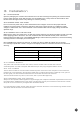
6. Technical Specifications RF Output Output frequency range Output frequency adjustment Output level Output level adjustment Output impedance Output return loss Spurious rejection Output frequency accuracy 48~860 MHz Min. step 10 kHz 95~120 dBμV Min. step by 1 dB 75Ω, F-type 12 dB min. 60 dBc min. VHF:±5 kHz, UHF:±10 kHz DVB-C QAM Modulation Constellation Symbol rate MER Spectrum inversion J.83A, 16, 32, 64, 128, 256QAM 2~7.2MS/s 36dB min.
En Constellation Tuner bandwidth Input signal level FFT mode Guard interval FEC code rate QPSK, 16-QAM, 64-QAM 6, 7 or 8MHz factory option -20~-75dBm 2K/8K, auto-detected 1/4, 1/8, 1/16 or 1/32, auto-detected 1/2, 2/3, 3/4, 5/6 or 7/8, auto-detected DS3 Input Input impedance Max. input bit rate Loop through output impedance Max. output bit rate Format 75Ω, BNC 44.736Mbps 75Ω, BNC 44.736Mbps Unframed or framed Framing according to G.804/G.752(DS3) TS over IP I/O Connector Max.
8. Safety CAUTION! Unauthorized maintenance or the use of non-approved replacements may affect the equipment specification and invalidate any warranties. Avoid any contact with liquid and corrosive substances Never attempt to disassemble the unit. Only trained and approved persons are permitted to service this unit.
En 21
FTA Communication Technologies 18 Duchscherstroos, L-6868 Wecker, Luxembourg Tel: +352 264 367 1 Fax: +352 264 313 68 e-mail: info@inverto.tv Web: www.inverto.