
Operation Manual


En
11
The 6 keys on the front panel allow you to navigate the information provided on the LCD and change parameters
when the device operates under local control.
The ENTER key is used to enter the main menu or a sub-menu. Inside a menu, ENTER is used to select the
parameter on the bottom line and to change its value. It also ends the input of new alphanumeric values and
conrms the changes.
The ▲ and ▼ keys are used to select between the main menus, sub-menus or programs. When a parameter is
selected inside a menu, they are also used to change its value. You may scroll through character positions using
the ◄ and ► keys. The EXIT key is used to exit a menu without any action taking place
4.5 COMMON INTERFACE
There are two Common Interface slots. You can insert up to two different CAM modules for descrambling.
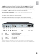
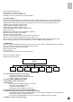
4.6 REAR PANEL & DEVICE CONNECTION
Always use the specied cables supplied for signal integrity and compliance with EMC requirements.
The rear panel is directly related to the input and output options tted. The gure below shows a typical rear
panel.
B1 RF Out RF signal output port
B2 TS/IP IP input/output port
B3 RS-232 Serial port for printing information
B4 LAN Control LAN port for software update
B5 ASI In ASI input port
B6,B7, ASI OUT Signals over ASI output port; B7 and B6 outputs are identical.
B8 Loop-through Tuner loop through signal
B9 TUNER IN Tuner input signal
B10 Power socket AC 90~250V input
Note:
This RS-232 interface is a 9-pins female sub-D connector that is only used for factory software upgrade and
conguration. You should not connect any cable to the RS-232 connector, as this may cause damage the device.